2023年“网络建设与运维”赛题解析
2023年“网络建设与运维”赛题解析
(一)交换配置
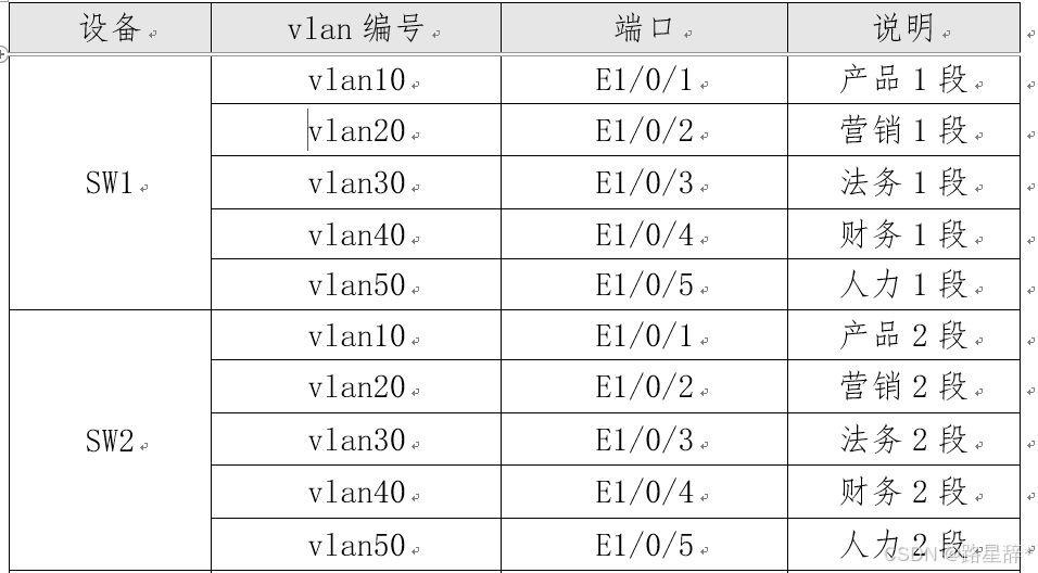
1.配置vlan,SW1、SW2、SW3、AC1的二层链路只允许相应vlan通过。
| 注意事项: (1)注意网段顺序是产品、营销、法务、财务、人力,端口对应是E1-5,VLAN对应是10、20,30,40,50;如下图所示:
(2)允许通过VLAN要根据实际需要而定。
|
2.SW1和SW2之间利用三条裸光缆实现互通,其中一条裸光缆承载三层IP业务、一条裸光缆承载VPN业务、一条裸光缆承载二层业务。用相关技术分别实现财务1段、财务2段业务路由表与其它业务路由表隔离,财务业务VPN实例名称为Finance。承载二层业务的只有一条裸光缆通道,配置相关技术,方便后续链路扩容与冗余备份,编号为1,用LACP协议,SW1为active,SW2为passive;采用源、目的IP进行实现流量负载分担。
| STEP 1:理清配置要求,画出拓扑示意图。
STEP 2:L3配置VLAN1022,对端地址是10.1.255.2;VPN是财务专线网段,地址与L3的地址一样,VLAN为1023;这两个地址配置已经在基础IP地址配置中完成配置任务。 STEP 3:L2业务需要配置LACP协议(链路聚合),在此要注意两点:(1)SW1为active,SW2为passive;(2)负载分担采用源、目的IP进行。 SW1配置: port-group 1 //创建编号为1的逻辑接口 interface e1/0/24 switchport mode trunk switchport trunk allowed vlan 10;20;30;40;50 port-group 1 mode active //绑定物理接口为主动端 load-balance dst-src-ip SW2配置: port-group 1 //创建编号为1的逻辑接口 interface e1/0/24 switchport mode trunk switchport trunk allowed vlan 10;20;30;40;50 port-group 1 mode passive //绑定物理接口为被动端 load-balance dst-src-ip |

3.SW3针对每个业务VLAN的第一个接口配置Loopback命令,模拟接口UP,方便后续业务验证与测试。
| STEP 1:理清配置思路,明确Loopback的作用;在SW-3的E1/0/1-3;5,11-12六个端口没有连接其他设备,对应的VLAN10,20,30,50,110,120处于关闭状态,为了开启端口,需要配置Loopback开启VLAN。 SW3配置: int e1/0/1-3;5;11-12 //进入需要划分到业务VLAN的端口 loopback //配置Loopback |
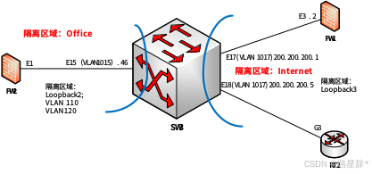
4.将SW3模拟为Internet交换机,实现与集团其它业务路由表隔离,Internet路由表VPN实例名称为Internet。将SW3模拟办事处交换机,实现与集团其它业务路由表隔离,办事处路由表VPN实例名称为Office。
| STEP 1:理清配置思路,画出示意图。
STEP 2:注意隔离区域配置:先创建VRF、VLAN,然后进入接口设定端口为VRF端口,接着配置IP地址及IPv6地址。 SW3配置: ip vrf Office //创建Internet实例 Int loopback2 ip vrf forwarding Office #配置 VRF 实例与接口关联 Ip add 10.1.3.2 255.255.255.255 Ipv6 add 2001:10:1:3::2/128 Int vlan 110 ip vrf forwarding Office Ip add 10.1.110.1 255.255.255.0 IPv6 add 2001:10:1:110::1/64 Int vlan 120 ip vrf forwarding Office Ip add 10.1.120.1 255.255.255.0 IPv6 add 2001:10:1:120::1/64 Int vlan 1015 ip vrf forwarding Office Ip add 10.1.255.46 255.255.255.252 VRF:Internet配置类似,在此省略。 |
5.SW1配置SNMP,引擎id分别为1000;创建组GroupSkills,采用最高安全级别,配置组的读、写视图分别为:Skills_R、Skills_W;创建认证用户为UserSkills,采用aes算法进行加密,密钥为Key-1122,哈希算法为sha,密钥为Key-1122;当设备有异常时,需要用本地的环回地址loopback1发送v3 Trap消息至集团网管服务器10.1.15.120、2001:10:1:15::120,采用最高安全级别;当法务部门对应的用户接口发生UP DOWN事件时禁止发送trap消息至上述集团网管服务器。
| STEP 1:理清配置思路,注意配置顺序。(1)启动snmp-server;(2)设置引擎id;(3)创建组;(4)创建用户;(5)开启snmp-server trap功能;(6)设置trap本地源;(7)设置trap目的地址;(8)当法务部门对应的用户接口发生UP DOWN事件时禁止发送trap消息至trap目的服务器。 SW1配置: (1)启用SNMP带领服务器 snmp-server enable (2)按要求配置引擎号 snmp-server engineid 1000 (3)按要求创建用户组 snmp-server group GroupSkills authpriv read Skills_R write Skills_W (4)按要求创建用户 snmp-server user UserSkills GroupSkills authPriv aes Key-1122 auth sha Key-1122 (5)按要求启用Trap参数配置 snmp-server enable traps //启用设备发送Trap消息功能 (6)按要求配置Trap源地址 snmp-server trap-source 10.1.1.1 // LoopBack1的IPv4地址 snmp-server trap-source 2001:10:1:1::1// LoopBack1的IPv6地址 (7)按要求配置Trap目的地址及用户 snmp-server host 10.1.15.120 v3 authpriv UserSkills //v3为最高安全等级 snmp-server host 2001:10:1:15::120 v3 authpriv UserSkills //v3为最高安全等级 (8)因为是最高安全级别,所以也需要设置一下安全ip,这个功能默认打开,只需要设置一下安全ip就行了(其实SNMPv3设置这个没有意义,防止扣分多做一下也没关系) snmp-server securityip 10.1.15.120 snmp-server securityip 2001:10:1:15::120 (9)接口发生UP DOWN事件时禁止发送trap消息至上述集团网管服务器 interface ethernet 1/0/3 no switchport updown notification enable |
6.对SW1与FW1互连流量镜像到SW1 E1/0/1,会话列表为1。
| STEP 1:本题仅仅考核一个镜像配置,不存在难点。 SW1配置: monitor session 1 source interface ethernet 1/0/19 both //指定源端口 monitor session 1 destination interface ethernet 1/0/1 //指定目的端口 |
| 知识延展:(2019年国赛题)集团预采购多个厂商网流分析平台对集团整体流量进行监控、审计,分别连接在两台核心交换机E1/0/10-E1/0/11接口测试,VLAN300作为远程端口镜像VLAN,Ethernet1/0/12作为反射端口,将核心交换机与接入交换机、路由器互连流量提供给多个厂商网流分析平台(18分)。 vlan 300 remote-span switchport interface e1/0/10-12 monitor session 1 remote vlan 300 #远程端口镜像VLAN monitor session 1 source interface e1/0/21;1/0/24 both #源端口 monitor session 1 reflector-port int e1/0/12 #反射端口,注意一下顺序 |
7.SW1和SW2 E1/0/21-28启用单向链路故障检测,当发生该故障时,端口标记为errdisable状态,自动关闭端口,经过1分钟后,端口自动重启;发送Hello报文时间间隔为15s。
| STEP 1:理清配置要求,理解配置任务。所谓单向链路,是指链路两端的端口之一可以收到对端发送的数据链路层报文,而对端不能收到本端发送的报文。ULDP(UniDirectional Link Detection Protocol)可以监控物理线路的链路状态,当发现单向链路后,向用户发送告警信息,并根据用户配置,自动或者手动地关闭相关端口。Errdisable表示自动回复,即属于积极模式。 配置思路:(1)启动全局 ULDP 功能;(2)配置 Recovery 时间间隔;(3)配置 Hello 报文时间间隔;(4)全局配置为积极模式;(5)进入端口,启用端口ULDP功能;(6)配置全局积极模式; SW1配置: uldp enable //全局启动ULDP uldp recovery-time 60 //经过1分钟后,端口自动重启 uldp hello-interval 15 //发送Hello报文时间间隔为15s uldp aggressive-mode //全局标记为errdisable(积极模式) interface ethernet 1/0/21-28 uldp enable //端口启动ULDP uldp aggressive-mode //端口标记为errdisable(积极模式) SW2的配置与SW1配置一样。 |
| 知识延展: 1.端口环路检测(loopback-detection); 2.链路层发现协议(Link Layer Discovery Protocol,LLDP); 3.LLDP-MED(Link Layer Discovery Protocol-Media Endpoint Discovery)以LLDP为基础; 4.Port Channel; 5.MTU; 6.bpdu-tunnel。 |
8.SW1和SW2所有端口启用链路层发现协议,更新报文发送时间间隔为20s,老化时间乘法器值为5,Trap报文发送间隔为10s,配置三条裸光缆端口使能Trap功能。
| STEP 1:理清配置思路,链路层发现协议(Link Layer Discovery Protocol,LLDP)是 802.1ab 中定义的新协议,它 可使邻近设备向其他设备发出其状态信息的通知,并且所有设备的每个端口上都存储着定义 自己的信息,如果需要还可以向与它们直接连接的近邻设备发送更新的信息,近邻的设备会 将信息存储在标准的 SNMP MIBs。 配置过程:(1)全局启动 LLDP 功能;(2)配置 LLDP 更新报文发送间隔;(3)配置 LLDP 报文老化时间乘法器;(4)配置 Trap 报文发送间隔;(5)配置基于端口的 LLDP 功能开关;(6)配置端口使能 Trap 功能。 SW1配置: lldp enable //全局启动或关闭 LLDP 功能 lldp tx-interval 20 //更新报文发送时间间隔为20s lldp msgTxHold 5 //老化时间乘法器值为5 lldp notification interval 10 // Trap报文发送间隔为10s int ethernet 1/0/1-28 lldp enable //所有端口启用链路层发现协议 int ethernet 1/0/22-24 lldp trap enable//三条裸光缆端口使能Trap功能 SW2的配置与SW1类似。 |
9.(非第1套题内容)配置SW1相关特性实现报文上送设备CPU的前端整体上对攻击报文进行拦截,开启日志记录功能,采样周期10s一次,恢复周期为120s,从而保障CPU稳定运行。
| STEP 1:理清配置思路。如果能在报文上送 CPU 的前端整体上对攻击报文进行拦截,将能够在更大程度上防护网络攻击,保障CPU的稳定运行。 配置过程:(1)开启CPU防护功能;(2)开启CPU防护日志记录;(3)开启CPU防护 trap 告警发送;(4)配置采样周期(显示用户配置的限速值);(5)配置CPU防护策略恢复。 SW1配置: cpu-protect enable cpu-protect log enable cpu-protect trap enable cpu-protect interval 10 cpu-protect recovery-time 120 |
10.(非第1套题内容)SW1法务物理接口限制收、发数据占用的带宽分别为100Mbps、90Mbps,限制所有报文最大收包速率为100packets/s,如果超过了配置交换机端口的报文最大收包速率则关闭此端口,10分钟后恢复此端口;启端口安全功能,只允许的最大安全MAC地址数为10,当超过设定MAC地址数量的最大值,不学习新的MAC、丢弃数据包、发snmp trap、同时在syslog日志中记录,端口的老化定时器到期后,在老化周期中没有流量的部分表项老化,有流量的部分依旧保留,恢复时间为10分钟;禁止采用访问控制列表,只允许IP主机位为20-30的数据包进行转发;禁止配置访问控制列表,实现端口间二层流量无法互通,组名称FW。
| STEP 1:理清配置要求,本题考核的内容主要针对法务端口,包含:(1)对法务端口的流控配置(flow control);(2)端口安全配置(switchport port-security);(3)通过am功能控制数据包转发;(4)实现端口间隔离(isolate-port)。 (1)完成流控配置(flow control); 打开端口 配置端口速率和双工模式 配置带宽控制 配置流量控制 设置交换机端口的报文最大收包速率 配置端口速率违背控制 (2)完成端口安全配置(switchport port-security); Protect模式:保护模式,不学习新的mac,丢弃数据包不告警 Restrict模式:限制模式,不学习新的mac,丢弃数据包,发送snmp trap,在syslog日志记录 Shutdown模式:关闭模式,默认模式,端口立即关闭,发送snmp trap,在日志记录 Type --absolute,到时间全部从mac表移除,inactivity有流量的保留 (3)通过am功能控制数据包转发; 启动 AM 功能 启动某端口的 AM 功能 配置转发 IP (4)实现端口间隔离(isolate-port)。 创建隔离组 将以太网端口添加进隔离组 指定需要隔离的流量 SW1配置: #流量控制 Int e1/0/3 speed-duplex force1g-full bandwidth control 100000 receive bandwidth control 90000 transmit flow control rate-violation all 100 rate-violation control shutdown recovery 600 #理论最小值是200 #端口安全 Mac-address-learning cpu-control #使能软件控制 mac 地址学习 Int e1/0/3 switchport port-security switchport port-security maximum 10 switchport port-security violation restrict #限制模式,不学习新的MAC,丢弃数据包,发snmp trap,同时在syslog日志中记录 switchport port-security aging type inactivity #端口的老化定时器到期,在老化周期中没有流量的部分表项老化,有流量的部分依旧保留 switchport port-security aging time 10 #恢复时间10分钟 #AM控制数据转发 Am enable #默认不启动AM功能 Int e1/0/3 am port #默认所有端口 AM 功能关闭 am ip-pool 10.1.13.20 11 #主要20-30共11个地址。 #实现法务流量的二层隔离 isolate-port apply l2 #是L2小写,该命令使端口隔离的配置应用于 2 层流量 isolate-port group FW isolate-port group FW switchport interface ethernet1/0/3 |
(二)路由调试
1.启用所有设备的ssh服务,防火墙用户名admin,明文密码Key-1122,其余设备用户名和明文密码均为admin。
| STEP 1:理清配置要求:所有设备指的是交换机(含AC)、路由器、防火墙; STEP 2:完成所有设备的配置: RT1、RT2配置: ip sshd enable //启用ssh服务 username admin password admin //设置用户名和密码 SW1、SW2、SW3、AC1配置: ssh-server enable //启用ssh服务 authentication line vty login local username admin password admin //设置用户名和密码 FW1、FW2配置: admin user admin access ssh password Key-1122 注意:防火墙设置用户名和密码,启用SSH服务只要在接口上启用就好(manage ssh),新的版本不需要这一步 |
2.配置所有设备的时区为GMT+08:00,调整SW1时间为实际时间,SW1配置为ntp server,其他设备用SW1 loopback1 ipv4地址作为ntp server地址,ntp client 请求报文时间间隔1分钟。
| STEP 1:理清配置要求:所有设备进行NTP配置,其中SW1为ntp server,且SW1 loopback1 ipv4地址作为ntp server地址,其余为NTP Client端。 NTP Server重点内容解析: 命令格式:ntp-service refclock-master [ip-address] [stratum] 参数说明:
STEP 2:配置NTP: (1)配置NTP Server: SW1配置: ntp enable //启用ntp服务 clock timezone GMT add 8 0 //设置时区 ntp-service refclock-master 15 //设置本地时钟作为NTP主时钟,提供同步时间 (2)配置NTP Client: SW2、SW3、AC1配置: NTP enable //启用ntp服务 clock timezone GMT add 8 0 //设置时区 NTP server 10.1.1.1 //设置ipv4 ntp服务器地址 NTP sys-interval 60 //设置客户端请求时间间隔 RT1、RT2配置: time-zone GMT 8 0 //设置时区 ntp query-interval 60 //设置客户端请求时间间隔 ntp server 10.1.1.1 //设置ipv4 ntp服务器地址 FW1、FW2配置: NTP enable //启用ntp服务 clock zone GMT 8 0 //设置时区 ntp query-interval 1 //设置客户端请求时间间隔,在此单位是分钟 ntp server 10.1.1.1 //设置ipv4 ntp服务器地址 ntp max-adjustment //设置最大同步时间 |
3.配置接口ipv4地址和ipv6地址,互联接口ipv6地址用本地链路地址。
| 知识点: 当路由设备与IPv6设备通信时,需要为接口配置IPv6地址。 链路本地地址用于邻居发现协议和无状态自动配置进程中链路本地节点之间的通信。使用链路本地地址作为源或目的地址的数据包不会被转发到其他链路上。 链路本地地址可以通过自动生成或手动配置两种方式获得:
因为链路本地地址只能用于链路本地节点之间的通信,通常用于满足协议的通信需求,与用户间的通信没有直接关系,所以推荐使用链路本地地址的自动生成方式。 |
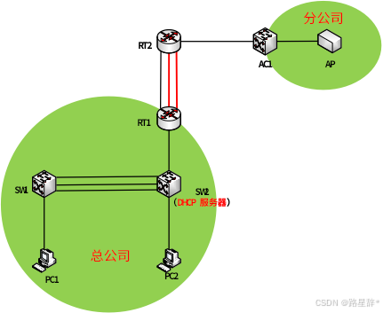
4.SW2配置DHCPv4和DHCPv6,分别为总公司产品1段、总公司产品2段、分公司Vlan130、分公司Vlan140和分公司Vlan150分配地址。IPv4地址池名称分别为Poolv4-Vlan11、Poolv4-Vlan21、Poolv4-Vlan130、Poolv4-Vlan140、Poolv4-Vlan150,排除网关,DNS为10.1.210.101和10.1.220.101。IPv6地址池名称分别为Poolv6-Vlan11、Poolv6-Vlan21、Poolv6-Vlan130、Poolv6-Vlan140、Poolv6-Vlan150,IPv6地址池用网络前缀表示,排除网关,DNS为2400:3200::1。PC1保留地址10.1.11.9和2001:10:1:11::9,PC2保留地址10.1.21.9和2001:10:1:21::9,AP1保留地址10.1.130.9和2001:10:1:130::9。SW1、AC1中继地址为SW2 Loopback1地址,SW1启用DHCPv4和DHCPv6 snooping,如果E1/0/1连接dhcpv4服务器,则关闭该端口,恢复时间为10分钟。
| STEP 1:理清思路,画出网络图。 首先明确DHCP服务器是SW2,为全网需要动态分配IP地址的网段分配IP地址。网络拓扑如下所示:
(1)根据题目要求,从拓扑图可以看出,应该在SW1和AC1上需要启用DHCP中继服务; (2)完成DHCP基础配置,包含DNS和排除地址; (3)针对PC1、PC2和无线AP完成保留地址配置; 注:获取AP的MAC方法是先在AC配置临时DHCP,然后获取到AP的MAC,最后,删除AC的临时DHCP. (4)在SW1中,完成IPv4和IPv6的Snooping配置。 STEP 2:在SW2完成IPv4和IPv6的DHCP基础配置: SW2配置: (1)通过在AC配置临时DHCP获取AP的MAC地址;同时,注意PC1和PC2的MAC地址获取。 (2)DHCPv4的基本配置 service dhcp Server dhcpv6 ip forward-protocol udp bootps ip dhcp pool Poolv4-Vlan11 //总公司产品1段 network-address 10.1.11.0 255.255.255.0 default-router 10.1.11.1 dns-server 10.1.210.101 10.1.220.101 ip dhcp pool Poolv4-Vlan21 //总公司产品2段 network-address 10.1.21.0 255.255.255.0 default-router 10.1.21.1 dns-server 10.1.210.101 10.1.220.101 ip dhcp pool Poolv4-Vlan130 //分公司管理VLAN network-address 10.1.130.0 255.255.255.0 default-router 10.1.130.1 dns-server 10.1.210.101 10.1.220.101 ip dhcp pool Poolv4-Vlan140 //分公司无线VLAN network-address 10.1.140.0 255.255.255.0 default-router 10.1.140.1 dns-server 10.1.210.101 10.1.220.101 ip dhcp pool Poolv4-Vlan150 //分公司无线VLAN network-address 10.1.150.0 255.255.255.0 default-router 10.1.150.1 dns-server 10.1.210.101 10.1.220.101 (3)IPv4排除网关地址 ip dhcp excluded-address 10.1.11.1 ip dhcp excluded-address 10.1.21.1 ip dhcp excluded-address 10.1.130.1 ip dhcp excluded-address 10.1.140.1 ip dhcp excluded-address 10.1.150.1 (4)IPv4的保留地址配置 ip dhcp pool PC1 host 10.1.11.9 255.255.255.0 //配置需要保留的IP和子网掩码 hardware-address 00-E0-4F-83-45-76 //绑定PC1的MAC地址 default-router 10.1.11.1 //让绑定设备获取网关地址 dns-server 10.1.210.101 10.1.220.101 //让绑定设备获取DNS地址 ip dhcp pool PC2 host 10.1.21.9 255.255.255.0 hardware-address E4-54-E8-C2-33-48 default-router 10.1.21.1 dns-server 10.1.210.101 10.1.220.101 ip dhcp pool AP1 host 10.1.130.9 255.255.255.0 hardware-address 00-03-0F-C1-A8-B0 default-router 10.1.130.1 dns-server 10.1.210.101 10.1.220.101 (5)配置DHCPv6 service dhcpv6 ipv6 dhcp pool Poolv6-Vlan11 network-address 2001:10:1:11::1 64 static-binding 2001:10:1:11::9 00-e0-4f-83-45-76 //PC1的IPv6地址绑定 excluded-address 2001:10:1:11::1 //排除IPv6地址 dns-server 2400:3200::1 ipv6 dhcp pool Poolv6-Vlan21 network-address 2001:10:1:21::1 64 static-binding 2001:10:1:21::9 e4-54-e8-c2-33-48 //PC2的IPv6地址绑定 excluded-address 2001:10:1:21::1 dns-server 2400:3200::1 ipv6 dhcp pool Poolv6-Vlan130 network-address 2001:10:1:130::1 64 static-binding 2001:10:1:130::9 00-03-0f-c1-a8-b0 excluded-address 2001:10:1:130::1 dns-server 2400:3200::1 ipv6 dhcp pool Poolv6-Vlan140 network-address 2001:10:1:140::1 64 excluded-address 2001:10:1:140::1 dns-server 2400:3200::1 ipv6 dhcp pool Poolv6-Vlan150 network-address 2001:10:1:150::1 64 excluded-address 2001:10:1:150::1 dns-server 2400:3200::1 (6)在接口上启用DHCPv6服务器功能 //在指定接口上启动DHCPv6服务器功能,并绑定使用的DHCPv6地址池。 interface Vlan 10 ipv6 dhcp server Poolv6-Vlan21 interface Vlan 1022 Ipv6 dhcp server Poolv6-Vlan11 interface Vlan 1019 ipv6 dhcp server Poolv6-Vlan130 ipv6 dhcp server Poolv6-Vlan140 //应该都要启用 ipv6 dhcp server Poolv6-Vlan150 //应该都要启用 STEP 3:在SW1配置IPv4和IPv6的DHCP中继及snooping SW1配置: (1)SW1的IPv4和IPv6的中继配置 Service dhcp Server dhcpv6 ip forward-protocol udp bootps interface Vlan 10 ip helper-address 10.1.2.1 //配置DHCPv4中继 ipv6 dhcp relay destination 2001:10:1:2::1 //配置DHCPv6中继 no ipv6 nd suppress-ra //开启IPv6路由器公告 ipv6 nd managed-config-flag //标识地址信息是否由 DHCPv6 获取 ipv6 nd other-config-flag //标识除地址信息之外的其他信息是否由DHCPv6获取 (2)SW1的监听配置 //SAVI(Source Address Validation Improvement)功能是一种提供节点源地址粒度级的安全 验证方式,它通过监听相关协议报文(如 ND 协议,DHCPv6 协议)的交互过程,利用 CPS (Control Packet Snooping)机制,提取节点可信任的信息(如端口,MAC 地址等信息)即锚信息,然后将 节点源地址与锚信息进行绑定,并下发绑定信息对应的过滤规则,放行匹配过滤规则的报文, 丢弃不匹配过滤规则的报文,从而达到对节点源地址合法性检测的目的。 savi enable savi ipv6 dhcp-only enable //使能 SAVI 应用场景功能 ip dhcp snooping enable interface ethernet 1/0/22 ip dhcp snooping trust //DHCPv4监听配置 ipv6 dhcp snooping trust //DHCPv6监听配置 //E1/0/1连接PC1,则关闭该端口,恢复时间为10分钟 interface ethernet 1/0/1 ip dhcp snooping action shutdown recovery 600 AC1配置:
Service dhcp Server dhcpv6 ip forward-protocol udp bootps interface Vlan 130 ip helper-address 10.1.2.1 ipv6 dhcp relay destination 2001:10:1:2::1 no ipv6 nd suppress-ra ipv6 nd managed-config-flag ipv6 nd other-config-flag interface Vlan 140 ip helper-address 10.1.2.1 ipv6 dhcp relay destination 2001:10:1:2::1 no ipv6 nd suppress-ra ipv6 nd managed-config-flag ipv6 nd other-config-flag interface Vlan 150 ip helper-address 10.1.2.1 ipv6 dhcp relay destination 2001:10:1:2::1 no ipv6 nd suppress-ra ipv6 nd managed-config-flag ipv6 nd other-config-flag |
5.SW1、SW2、SW3、RT1以太链路、RT2以太链路、FW1、FW2、AC1之间运行OSPFv2和OSPFv3协议(路由模式发布网络用接口地址,BGP协议除外)。
(1)SW1、SW2、SW3、RT1、RT2、FW1之间OSPFv2和OSPFv3协议,进程1,区域0,分别发布loopback1地址路由和产品路由,FW1通告type1默认路由。
(2)RT2与AC1之间运行OSPFv2协议,进程1,nssa no-summary区域1;AC1发布loopback1地址路由、产品和营销路由,用prefix-list重发布loopback3。
(3)RT2与AC1之间运行OSPFv3协议,进程1,stub no-summary区域1;AC1发布loopback1地址路由、产品和营销。
(4)SW3模拟办事处产品和营销接口配置为loopback,模拟接口up。SW3模拟办事处与FW2之间运行OSPFv2协议,进程2,区域2,SW3模拟办事处发布loopback2、产品和营销。SW3模拟办事处配置ipv6默认路由;FW2分别配置到SW3模拟办事处loopback2、产品和营销的ipv6明细静态路由,FW2重发布静态路由到OSPFv3协议。
(5)RT1、FW2之间OSPFv2和OSPFv3协议,进程2,区域2;RT1发布loopback4路由,向该区域通告type1默认路由;FW2发布loopback1路由,FW2禁止学习到集团和分公司的所有路由。RT1用prefix-list匹配FW2 loopback1路由、SW3模拟办事处loopback2和产品路由、RT1与FW2直连ipv4路由,将这些路由重发布到区域0。
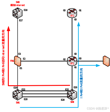
(6)修改ospf cost为100,实现SW1分别与RT2、FW2之间ipv4和ipv6互访流量优先通过SW1_SW2_RT1链路转发,SW2访问Internet ipv4和ipv6流量优先通过SW2_SW1_FW1链路转发。
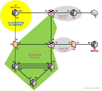
| STEP 1:理清配置要求,画出配置拓扑图,理解OSPFv2和OSPFv3的不同配置面的概念。
根据题目要求,明晰配置进程: (1)完成OSPFv2的基础配置和OSPFv3的基础配置; (2)完成OSPFv2的功能性配置和OSPFv3的功能型配置; (3)完成OSPFv2和OSPFv3的选路配置,即cost值设置。 STEP 2:根据题目要求完成配置。 (1)完成OSPFv2的基础配置和OSPFv3的基础配置; 完成基础配置要先进程顺序,然后区域顺序的原则进行配置;在此配置顺序是:SW1、SW2、SW3、FW1àRT2、AC1àRT1、FW2 SW1配置: 注意:Loopback1的IP地址是10.1.1.1/32,产品是:10.1.11.0/24;SW1连接SW2(1022-1022,10.1.255.0/30),SW3(1020-1019,10.1.255.4/30),连接FW1(1019,10.1.255.12/30),IPv6地址按规律表示。 router ospf 1 //配置OSPFv2 router-id 10.1.1.1 network 10.1.1.1/32 area 0 network 10.1.11.0/24 area 0 network 10.1.255.0/30 area 0 //连接SW2 network 10.1.255.4/30 area 0 //连接SW3 network 10.1.255.12/30 area 0 //连接FW1 router ipv6 ospf //启用OSPFv3 router-id 10.1.1.1 interface Loopback1 //loopback1开启IPv6的OSPFv3配置 ipv6 router ospf area 0 //端口启用OSPFv3,通告网络 interface Vlan10 //产品1段(VLAN10)开启IPv6的OSPFv3配置 ipv6 router ospf area 0 interface Vlan1019 //连接FW1的端口开启IPv6的OSPFv3配置 ipv6 router ospf area 0 interface Vlan1020 //连接SW3的端口开启IPv6的OSPFv3配置 ipv6 router ospf area 0 interface Vlan1022 //连接SW2的端口开启IPv6的OSPFv3配置 ipv6 router ospf area 0 SW2配置: 注意:Loopback1的IP地址是10.1.2.1/32,产品是:10.1.21.0/24;SW1连接SW1(1022-1022,10.1.255.0/30),SW3(1020-1020,10.1.255.8/30),连接FW1(1019-RT1,10.1.255.20/30),IPv6地址按规律表示。 router ospf 1 //配置OSPFv2 router-id 10.1.2.1 network 10.1.2.1/32 area 0 network 10.1.21.0/24 area 0 network 10.1.255.0/30 area 0 network 10.1.255.8/30 area 0 network 10.1.255.20/30 area 0 router ipv6 ospf //配置OSPFv3 router-id 10.1.2.1 interface Loopback1 ipv6 router ospf area 0 interface Vlan10 ipv6 router ospf area 0 interface Vlan1019 //连接RT1的端口开启IPv6的OSPFv3配置 ipv6 router ospf area 0 interface Vlan1020 ipv6 router ospf area 0 interface Vlan1022 ipv6 router ospf area 0 SW3配置: 注意:Loopback1的IP地址是10.1.3.1/32,产品是:10.1.31.0/24;SW1连接SW1(1019-1020,10.1.255.4/30),SW2(1020-1020,10.1.255.8/30), IPv6地址按规律表示。 router ospf 1 router-id 10.1.3.1 network 10.1.3.1/32 area 0 network 10.1.31.0/24 area 0 network 10.1.255.4/30 area 0 network 10.1.255.8/30 area 0 router ipv6 ospf router-id 10.1.3.1 interface Loopback1 ipv6 router ospf area 0 interface Vlan10 ipv6 router ospf area 0 interface Vlan1019 ipv6 router ospf area 0 interface Vlan1020 ipv6 router ospf area 0 FW1配置: 注意:Loopback1的IP地址是10.1.7.1/32,没有产品网段;RT1连接SW1(E0/1-1019,10.1.255.12/30),连接FW1(E0/2-G0/2,10.1.255.16/30),IPv6地址按规律表示。 ip vrouter trust-vr router ospf 1 router-id 10.1.7.1 network 10.1.7.1/32 area 0 network 10.1.255.12/30 area 0 network 10.1.255.16/30 area 0 ipv6 router ospf router-id 10.1.7.1 interface loopback1 ipv6 ospf area 0 interface ethernet0/1 ipv6 ospf area 0 interface ethernet0/2 ipv6 ospf area 0 RT2配置: 注意:Loopback1的IP地址是10.1.6.1/32,没有产品网段;RT1连接RT1(G0/0-G0/0,10.1.255.28/30),IPv6地址按规律表示。 router ospf 1 router-id 10.1.6.1 network 10.1.6.1 255.255.255.255 area 0 network 10.1.255.28 255.255.255.252 area 0 network 10.1.255.40 255.255.255.252 area 1 //通告OSPFv2区域1
ipv6 unicast-routing //打开接口的ipv6转发功能 router ospfv3 1 router-id 10.1.6.1 interface Loopback1 ipv6 ospf 1 area 0 interface GigaEthernet0/0 ipv6 ospf 1 area 0 AC1配置: 注意:AC1配置需要设定Router-ID。发布LoopBack1(10.1.4.1/32),产品网络(10.1.140.0/24)、营销网络(10.1.150.0/24)。 router ospf 1 router-id 10.1.4.1 network 10.1.4.1/32 area 1 network 10.1.255.40/30 area 1 network 10.1.130.0/24 area 1 network 10.1.140.0/24 area 1 network 10.1.150.0/24 area 1 RT1配置: 注意:Loopback1的IP地址是10.1.5.1/32,没有产品网段;RT1连接SW2(G0/1-1019,10.1.255.20/30),连接RT2(G0/0-G0/0,10.1.255.28/30),连接FW1(G0/2-E0/2,10.1.255.16/30),IPv6地址按规律表示;特别注意不要把进程2区域2配置漏了。 router ospf 1 router-id 10.1.5.1 network 10.1.5.1 255.255.255.255 area 0 network 10.1.255.20 255.255.255.252 area 0 network 10.1.255.28 255.255.255.252 area 0 network 10.1.255.16 255.255.255.252 area 0 ipv6 unicast-routing //打开接口的ipv6转发功能 router ospfv3 1 router-id 10.1.5.1 interface Loopback1 ipv6 ospf 1 area 0 interface GigaEthernet0/0 ipv6 ospf 1 area 0 interface GigaEthernet0/1 ipv6 ospf 1 area 0 interface GigaEthernet0/2 ipv6 ospf 1 area 0 router ospf 2 //OSPFv2进程2 router-id 10.1.5.4 network 10.1.5.4 255.255.255.255 area 2 network 10.1.255.24 255.255.255.252 area 2 router ospfv3 2 //OSPFv3进程2 router-id 10.1.5.4 interface Loopback4 ipv6 ospf 2 area 2 interface GigaEthernet0/3 ipv6 ospf 2 area 2 FW2配置: 注意OSPFv6的配置。 ip vrouter trust-vr router ospf 2 router-id 10.1.8.1 network 10.1.8.1/32 area 2 network 10.1.255.24/30 area 2 ipv6 router ospf router-id 10.1.8.1 interface loopback1 ipv6 ospf area 2 interface ethernet0/2 ipv6 ospf area 2 (2)完成OSPFv2的功能性配置和OSPFv3的功能型配置 完成(1)题的在FW1通告type1默认路由 FW2配置: ip vrouter trust-vr ip route 0.0.0.0/0 200.200.200.1 //为了访问Internet服务。 Ipv6 route ::/0 ethernet0/3 FE80::203:FFF:FEBD:C706 //这个不能漏了 router ospf 1 default-information originate always type 1 //通告type1默认路由 ipv6 router ospf default-information originate always type 1 //通告type1默认路由 完成(2)和(3)题完全末节区域配置和利用前缀发布loopback3 RT2配置: router ospf 1 area 1 nssa no-summary //设置区域1为nssa no-summary区域 router ospfv3 1 area 1 stub no-summary //设置区域1为stub no-summary区域 AC1配置: ip prefix-list Lo3 permit 10.1.4.3/32 //使用前缀定义ipv4流量 route-map Lo3 permit 10 //将定义的ipv4流量用route-map套用 match ip address prefix-list Lo3 router ospf 1 area 1 nssa no-summary //设置区域1为nssa no-summary区域 redistribute connect route-map Lo3 //将Loopback3重分布到ospf 1 router ipv6 ospf area 1 stub no-summary //设置区域1为stub no-summary区域 完成(4)题模拟办事处SW3的产品和营销的loopback配置和IPv6默认路由配置;FW2到模拟办事处的loopback2、产品和营销的IPv6明细静态路由及FW2重发布静态路由 SW3配置: int ethernet 1/0/11-12 loopback //配置ipv6默认路由指向对方端口,对端端口为自动IPv6链路地址,注意如何获取 //格式:ipv6 route <⽬标IPv6前缀> <出站接⼝> <下⼀跳IPv6地址> ipv6 route vrf Office ::/0 fe80::203:fff:fea5:a4c1 vlan1015 FW2配置: ip vrouter trust-vr //VLAN1015地址 ipv6 route 2001:10:1:3::2/128 ethernet0/1 FE80::203:FFF:FEBD:C706 //配置ipv6静态路由 ipv6 route 2001:10:1:110::/64 ethernet0/1 FE80::203:FFF:FEBD:C706 ipv6 route 2001:10:1:120::/64 ethernet0/1 FE80::203:FFF:FEBD:C706 ipv6 router ospf //把IPv6静态路由引入 redistribute static 完成(5)题RT1向进程2通告type1默认路由;RT1通过前缀发布FW2的loopback1、模拟办事处SW3的Loopback2和产品路由、RT1与FW2直连IPv4路由,将这路由重发布到区域0。 RT1配置: router ospf 2 default-information originate always metric-type 1 //通过type1默认路由 router ospfv3 2 default-information originate always metric-type 1 //通过type1默认路由 //使用前缀定义ipv4流量 ip prefix-list P1 permit 10.1.8.1/32 //FW1的loopback1 ip prefix-list P1 permit 10.1.3.2/32 //SW3模拟办事处的loopback2 ip prefix-list P1 permit 10.1.110.0/24 //SW3办事处的产品 ip prefix-list P1 permit 10.1.255.24/30 //与FW2的直连网络 route-map M1 permit //将定义的ipv4流量用route-map套用 match ip address prefix-list P1 router ospf 1 redistribute ospf 2 route-map M1 //将ospf 2指定ipv4流量重分布到ospf 1 redistribute connect route-map M1 //将直连指定ipv4流量重分布到ospf 1 (3)完成OSPFv2和OSPFv3的选路配置,即cost值设置。 画出示意拓扑图 从图示,很明显只要在RT1和FW1的链路开销修改为100即可。
RT1配置: interface GigaEthernet0/2 ip ospf cost 100 //IPv4的开销为100 ipv6 ospf cost 100 //IPv6的开销为100 FW1配置: Interface e0/2 ip ospf cost 100 ipv6 ospf cost 100 路由信息结果分析 (1)到RT2、AC1、FW2的路由 (2)到FW1的默认路由下一跳。 |
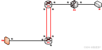
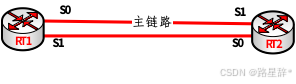
6.RT1串行链路、RT2串行链路、FW1、AC1之间分别运行RIP和RIPng协议,FW1、RT1、RT2的RIP和RIPng发布loopback2地址路由,AC1 RIP发布loopback2地址路由,AC1 RIPng采用route-map匹配prefix-list重发布loopback2地址路由。RT1配置offset值为3的路由策略,实现RT1-S1/0_RT2-S1/1为主链路,RT1-S1/1_RT2-S1/0为备份链路,ipv4的ACL名称为AclRIP,ipv6的ACL名称为AclRIPng。RT1的S1/0与RT2的S1/1之间采用chap双向认证,用户名为对端设备名称,密码为Key-1122。
| STEP 1:根据题目要求,画出拓扑图。
(1)完成RIP和RIPng的基础配置,即FW1、RT1、RT2和AC1发布Loopback2的IPv4和IPv6地址,只是注意在AC1中RIP的loopback2直接发布,RIPng发布通过前缀发布。 (2)RT1和RT2之间完成RIP和RIPng的选路配置。 (3)在RT1的S1/0和RT2的S1/1链路配置CHAP双向认证,用户名为对端设备名称,密码为Key-1122。 STEP 2:按步骤完成配置。 (1)完成RIP和RIPng的基础配置 RT1配置: router rip 1 //启用RIP进程 version 2 //选择版本2 no auto-summary //关闭自动汇总 router ripng 1 //启用RIPng进程 interface Loopback2 ip rip 1 enable //RIP通告网络 ipv6 rip 1 enable //RIPng通告网络 interface Serial1/0 ip rip 1 enable ipv6 rip 1 enable interface Serial1/1 ip rip 1 enable ipv6 rip 1 enable interface GigaEthernet0/2 //连接FW1的接口 ip rip 1 enable ipv6 rip 1 enable RT2配置: router rip 1 version 2 no auto-summary router ripng 1 interface Loopback2 ip rip 1 enable ipv6 rip 1 enable interface Serial1/0 ip rip 1 enable ipv6 rip 1 enable interface Serial1/1 ip rip 1 enable ipv6 rip 1 enable interface GigaEthernet0/1 //连接AC1的接口 ip rip 1 enable ipv6 rip 1 enable FW1配置: ip vrouter trust-vr router rip //启用RIP network 10.1.7.2/32 //通告Loopback2网络 network 10.1.255.16/30 ipv6 router rip //启用RIPng network loopback2 //通告Loopback2网络 network ethernet0/2 AC1配置: router rip //启用RIP network 10.1.4.2/32 //通告Loopback2网络 network 10.1.255.40/30 //使用前缀定义ipv6流量 ipv6 prefix-list l2 permit 2001:10:1:4::2/64 //使用前缀定义ipv6流量 route-map L2 permit 10 //将定义的ipv6流量用route-map套用 match ipv6 address prefix-list L2 router ipv6 rip //启用RIPng redistribute connected route-map L2 //将直连L2的ipv6流量重分布到RIPng
interface Vlan1001 ipv6 router rip //RIPng通告流量 (2)RT1和RT2之间完成RIP和RIPng的选路配置
注意:题目要求只能在RT1上配置 RT1配置: ip access-list standard AclRIP //使用ACL允许所有ipv4流量 permit any router rip 1 //增大IPv4流量经S1/1进出的跳数,确保进出流量走S1/0 offset Serial1/1 in AclRIP 3 offset Serial1/1 out AclRIP 3 ipv6 access-list AclRIPng //使用ACL允许所有ipv6流量 permit ipv6 any any router ripng 1 //增大IPv6流量经S1/1进出的跳数,确保进出流量走S1/0 offset Serial1/1 in AclRIPng 3 offset Serial1/1 out AclRIPng 3 (3)在RT1的S1/0和RT2的S1/1链路配置CHAP双向认证,用户名为对端设备名称,密码为Key-1122。 RT1配置: 是否需要启用本地认证? username RT1 password Key-1122 //配置身份识别 interface Serial1/0 //配置主链路CHAP双向认证 encapsulation ppp ppp authentication chap //启用chap认证 ppp chap hostname RT2 //发送用户名 ppp chap password Key-1122 //发送自身的密码 RT2配置: username RT2 password Key-1122 interface Serial1/1 encapsulation ppp ppp authentication chap ppp chap hostname RT1 ppp chap password Key-1122 |
7.RT1以太链路、RT2以太链路之间运行ISIS协议,进程1,分别实现loopback3 之间ipv4互通和ipv6互通。RT1、RT2的NET分别为10.0000.0000.0001.00、10.0000.0000.0002.00,路由器类型是Level-2,接口网络类型为点到点。配置域md5认证和接口md5认证,密码均为Key-1122。
| STEP 1:明晰配置要求,完善配置内容,画出拓扑图。
知识要点: 1.RT1与RT2之间配置ISIS。因此,必须对ISIS配置熟悉:中间系统到中间系统的路由选择协议(IS-IS)是由 ISO 提出的一种路由选择协议。 1)激活IS-IS,最基础配置 router isis 1 //激活IS-IS路由协议 net 10. 0000.0000.0001.00 //配置网络实体标题(NET) interface interface-name 进入接口配置态 ip router isis 1 //在接口上关联IS-IS进程 2)配置 IS-IS 路由器级别 router isis 1 is-type [level-1|level-1-2|level-2-only] //配置路由器类型,确省为level-1-2 interface interface-name //进入接口配置态 isis circuit-type level-1|level-1-2| level-2-only //与定义类型一致,缺省为level-1 3)配置 IS-IS 接口网络类型 isis network [ broadcast|point-to-point ] //这个命令配置IS-IS的接口网络类型。 4)配置 domain 区域验证 router isis 1 //从全局配置态进入IS-IS路由配置态 domain-password WORD [authenticate snp send-only|validate] 5)配置邻接关系验证 interface interface-name //分别对level-1和level-2的接口配置邻接认证密码,缺省同时对level-1和level-2生效 STEP 2:完成ISIS的IPv4和IPv6的配置。 RT1配置: router isis 1 is-type level-2 //配置路由器类型为Level-2 authentication mode md5 level-2 //配置域md5认证 authentication key 0 Key-1122 level-2 net 10.0000.0000.0001.00 interface Loopback3 ip router isis 1 //启用ipv4的ISIS ipv6 router isis 1 //启用ipv6的ISIS isis circuit-type level-2 interface GigaEthernet0/0 ip router isis 1 ipv6 router isis 1 isis network point-to-point //接口网络类型为点到点 isis circuit-type level-2 //路由器类型为Level-2 isis authentication mode md5 level-2 //接口md5认证 isis authentication key 0 Key-1122 level-2 RT2配置: router isis 1 is-type level-2 authentication mode md5 level-2 authentication key 0 Key-1122 level-2 net 10.0000.0000.0002.00 interface Loopback3 ip router isis 1 ipv6 router isis 1 isis circuit-type level-2 interface GigaEthernet0/0 ip router isis 1 ipv6 router isis 1 isis network point-to-point isis circuit-type level-2 isis authentication mode md5 isis authentication key 0 Key-1122 level-2 |

8.RT2配置ipv4 nat,实现AC1 ipv4产品用RT2外网接口ipv4地址访问Internet。RT2配置nat64,实现AC1 ipv6产品用RT2外网接口ipv4地址访问Internet,ipv4地址转ipv6地址前缀为64:ff9b::/96。
| STEP 1:根据题意 任务1. 在RT2上做NAT为AC1的产品IPv4用户访问Internet服务; 任务2. 在RT2上做NAT64实现AC1的产品IPv6用户通过外网口IPv4访问Internet,IPv4地址转化为IPv6地址前缀为64:ff96::/96 网络拓扑结构如下所示:
STEP 2:完成配置任务 RT2配置: 第1步:完成配置准备 Ip route default 200.200.200.5 //配置指向外网的默认路由 注意:为什么不进行注入默认路由,在OSPF配置时已经在FW1注入默认路由了,不可以重复注入。 第2步:配置IPv4和IPv6的NAT转换的约定范围(ACL) ip access-list standard nat4 permit 10.1.140.0 255.255.255.0 //IPv4的ACL //通过ACL约定NAT64访问规则 ipv6 access-list nat6 permit ipv6 2001:10:1:140::/64 64:FF9B::/96 //约定NAT64访问规则 ipv6 nat prefix 64:FF9B::/96 v4-mapped nat6 //ipv4地址转ipv6地址前缀 第3步:配置NAT转换规则 ip nat inside source list nat4 interface GigaEthernet0/3 //IPv4转换规则 ipv6 nat v6v4 source list nat6 interface GigaEthernet0/3 //IPv6转换规则 第4步:指定NAT的内外接口 interface GigaEthernet0/1 ip nat inside //IPv4内网接口 ipv6 nat //IPv6内网接口 interface GigaEthernet0/3 ip nat outside //IPv4外网接口 ipv6 nat //IPv6外网接口
STEP 2:进行测试 AC1#ping6 src 2001:10:1:140::1 64:ff9b::200.200.3.3 Type ^c to abort. Sending 5 56-byte ICMP Echos to 64:ff9b::200.200.3.3, using src address 2001:10:1:140::1, timeout is 2 seconds. !!!!! Success rate is 100 percent (5/5), round-trip min/avg/max = 0/10/20 ms |

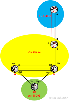
9.SW1、SW2、SW3、RT1、RT2之间运行BGP协议,SW1、SW2、RT1 AS号65001、RT2 AS号65002、SW3 AS号65003。
(1)SW1、SW2、SW3、RT1、RT2之间通过loopback1建立ipv4和ipv6 BGP邻居。SW1和SW2之间财务通过loopback2建立ipv4和ipv6 BGP邻居,SW1和SW2的loopback2互通采用静态路由。(2)SW1、SW2、SW3、RT2分别只发布营销、法务、财务、人力等ipv4和ipv6路由;RT1发布办事处营销ipv4和ipv6路由到BGP。
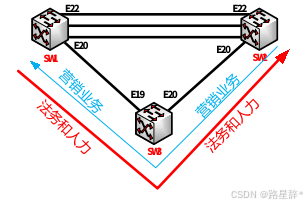
(3)SW3营销分别与SW1和SW2营销ipv4和ipv6互访优先在SW3_SW1链路转发;SW3法务及人力分别与SW1和SW2法务及人力ipv4和ipv6互访优先在SW3_SW2链路转发,主备链路相互备份;用prefix-list、route-map和BGP路径属性进行选路,新增AS 65000。
| STEP 1:根据题目要求,可以画出网络拓扑图如下
STEP 2:根据配置要求,完成BGP基础配置 第1步:根据(1)要求,完成BGP基础配置 配置要求: 1)BGP配置包含建立邻居关系、指定邻居关系更新源、建立ebgp邻居关系及更新源。 2)BGP配置中,在IPv4中取消IPv6的激活,在IPv6中再进行激活。 3)不同区域之间需要配置ebgp-multihop 255,用于不同区域之间交换路由信息。 4)财务是在独立的VRF区域内的配置,在此仅要求配置IPv4的邻居关系,之后需要拓展一下知识,若需要配置IPv6邻居关系如何配置。 SW1配置: router bgp 65001 //启用BGP,as为65001 bgp router-id 10.1.1.1 //设置BGP的router-id neighbor 10.1.2.1 remote-as 65001 //建立IPv4邻居关系 neighbor 10.1.3.1 remote-as 65003 neighbor 10.1.5.1 remote-as 65001 neighbor 10.1.6.1 remote-as 65002 neighbor 2001:10:1:2::1 remote-as 65001 //建立IPv6邻居关系 neighbor 2001:10:1:3::1 remote-as 65003 neighbor 2001:10:1:5::1 remote-as 65001 neighbor 2001:10:1:6::1 remote-as 65002 neighbor 10.1.2.1 update-source 10.1.1.1 //指定IPv4更新源 neighbor 10.1.3.1 update-source 10.1.1.1 neighbor 10.1.5.1 update-source 10.1.1.1 neighbor 10.1.6.1 update-source 10.1.1.1 neighbor 2001:10:1:2::1 update-source 2001:10:1:1::1 //指定更新源 neighbor 2001:10:1:3::1 update-source 2001:10:1:1::1 neighbor 2001:10:1:5::1 update-source 2001:10:1:1::1 neighbor 2001:10:1:6::1 update-source 2001:10:1:1::1 neighbor 10.1.3.1 ebgp-multihop 255 //与ebgp建立IPv4邻居关系 neighbor 10.1.6.1 ebgp-multihop 255 neighbor 2001:10:1:3::1 ebgp-multihop 255 //与ebgp建立IPv6邻居关系 neighbor 2001:10:1:6::1 ebgp-multihop 255 no neighbor 2001:10:1:2::1 activate //在ipv4中取消IPv6激活 no neighbor 2001:10:1:3::1 activate no neighbor 2001:10:1:5::1 activate no neighbor 2001:10:1:6::1 activate neighbor 10.1.2.1 next-hop-self //与IBGP指定下一跳配置 neighbor 10.1.5.1 next-hop-self address-family ipv6 neighbor 2001:10:1:2::1 activate //在ipv6中激活
neighbor 2001:10:1:3::1 activate neighbor 2001:10:1:5::1 activate neighbor 2001:10:1:6::1 activate neighbor 2001:10:1:2::1 next-hop-self neighbor 2001:10:1:5::1 next-hop-self SW2配置: router bgp 65001 bgp router-id 10.1.2.1 neighbor 10.1.1.1 remote-as 65001 neighbor 10.1.3.1 remote-as 65003 neighbor 10.1.5.1 remote-as 65001 neighbor 10.1.6.1 remote-as 65002 neighbor 2001:10:1:1::1 remote-as 65001 neighbor 2001:10:1:3::1 remote-as 65003 neighbor 2001:10:1:5::1 remote-as 65001 neighbor 2001:10:1:6::1 remote-as 65002 neighbor 10.1.1.1 update-source 10.1.2.1 neighbor 10.1.3.1 update-source 10.1.2.1 neighbor 10.1.5.1 update-source 10.1.2.1 neighbor 10.1.6.1 update-source 10.1.2.1 neighbor 2001:10:1:1::1 update-source 2001:10:1:2::1 neighbor 2001:10:1:3::1 update-source 2001:10:1:2::1 neighbor 2001:10:1:5::1 update-source 2001:10:1:2::1 neighbor 2001:10:1:6::1 update-source 2001:10:1:2::1 neighbor 10.1.3.1 ebgp-multihop 255 neighbor 10.1.6.1 ebgp-multihop 255 neighbor 2001:10:1:3::1 ebgp-multihop 255 neighbor 2001:10:1:6::1 ebgp-multihop 255 no neighbor 2001:10:1:1::1 activate no neighbor 2001:10:1:3::1 activate no neighbor 2001:10:1:5::1 activate no neighbor 2001:10:1:6::1 activate neighbor 10.1.1.1 next-hop-self neighbor 10.1.5.1 next-hop-self address-family ipv6 neighbor 2001:10:1:1::1 activate neighbor 2001:10:1:3::1 activate neighbor 2001:10:1:5::1 activate neighbor 2001:10:1:6::1 activate neighbor 2001:10:1:1::1 next-hop-self neighbor 2001:10:1:5::1 next-hop-self SW3配置: router bgp 65003 bgp router-id 10.1.3.1 neighbor 10.1.1.1 remote-as 65001 neighbor 10.1.2.1 remote-as 65001 neighbor 10.1.5.1 remote-as 65001 neighbor 10.1.6.1 remote-as 65002 neighbor 2001:10:1:1::1 remote-as 65001 neighbor 2001:10:1:2::1 remote-as 65001 neighbor 2001:10:1:5::1 remote-as 65001 neighbor 2001:10:1:6::1 remote-as 65002 neighbor 10.1.1.1 update-source 10.1.3.1 neighbor 10.1.2.1 update-source 10.1.3.1 neighbor 10.1.5.1 update-source 10.1.3.1 neighbor 10.1.6.1 update-source 10.1.3.1 neighbor 2001:10:1:1::1 update-source 2001:10:1:3::1 neighbor 2001:10:1:2::1 update-source 2001:10:1:3::1 neighbor 2001:10:1:5::1 update-source 2001:10:1:3::1 neighbor 2001:10:1:6::1 update-source 2001:10:1:3::1 neighbor 10.1.1.1 ebgp-multihop 255 neighbor 10.1.2.1 ebgp-multihop 255 neighbor 10.1.5.1 ebgp-multihop 255 neighbor 10.1.6.1 ebgp-multihop 255 neighbor 2001:10:1:1::1 ebgp-multihop 255 neighbor 2001:10:1:2::1 ebgp-multihop 255 neighbor 2001:10:1:5::1 ebgp-multihop 255 neighbor 2001:10:1:6::1 ebgp-multihop 255 no neighbor 2001:10:1:1::1 activate no neighbor 2001:10:1:2::1 activate no neighbor 2001:10:1:5::1 activate no neighbor 2001:10:1:6::1 activate address-family ipv6 neighbor 2001:10:1:1::1 activate neighbor 2001:10:1:2::1 activate neighbor 2001:10:1:5::1 activate neighbor 2001:10:1:6::1 activate RT1配置: router bgp 65001 bgp router-id 10.1.5.1 neighbor 10.1.1.1 remote-as 65001 neighbor 10.1.2.1 remote-as 65001 neighbor 10.1.3.1 remote-as 65003 neighbor 10.1.6.1 remote-as 65002 neighbor 2001:10:1:1::1 remote-as 65001 neighbor 2001:10:1:2::1 remote-as 65001 neighbor 2001:10:1:3::1 remote-as 65003 neighbor 2001:10:1:6::1 remote-as 65002 neighbor 10.1.1.1 update-source 10.1.5.1 neighbor 10.1.2.1 update-source 10.1.5.1 neighbor 10.1.3.1 update-source 10.1.5.1 neighbor 10.1.6.1 update-source 10.1.5.1 neighbor 2001:10:1:1::1 update-source 2001:10:1:5::1 neighbor 2001:10:1:2::1 update-source 2001:10:1:5::1 neighbor 2001:10:1:3::1 update-source 2001:10:1:5::1 neighbor 2001:10:1:6::1 update-source 2001:10:1:5::1 neighbor 10.1.3.1 ebgp-multihop 255 neighbor 10.1.6.1 ebgp-multihop 255 neighbor 2001:10:1:3::1 ebgp-multihop 255 neighbor 2001:10:1:6::1 ebgp-multihop 255 no neighbor 2001:10:1:1::1 activate no neighbor 2001:10:1:2::1 activate no neighbor 2001:10:1:3::1 activate no neighbor 2001:10:1:6::1 activate neighbor 10.1.1.1 next-hop-self neighbor 10.1.2.1 next-hop-self address-family ipv6 neighbor 2001:10:1:1::1 activate neighbor 2001:10:1:2::1 activate neighbor 2001:10:1:3::1 activate neighbor 2001:10:1:6::1 activate neighbor 2001:10:1:1::1 next-hop-self neighbor 2001:10:1:2::1 next-hop-self RT2配置: router bgp 65002 bgp router-id 10.1.6.1 neighbor 10.1.1.1 remote-as 65001 neighbor 10.1.2.1 remote-as 65001 neighbor 10.1.3.1 remote-as 65003 neighbor 10.1.5.1 remote-as 65001 neighbor 2001:10:1:1::1 remote-as 65001 neighbor 2001:10:1:2::1 remote-as 65001 neighbor 2001:10:1:3::1 remote-as 65003 neighbor 2001:10:1:5::1 remote-as 65001 neighbor 10.1.1.1 update-source 10.1.6.1 neighbor 10.1.2.1 update-source 10.1.6.1 neighbor 10.1.3.1 update-source 10.1.6.1 neighbor 10.1.5.1 update-source 10.1.6.1 neighbor 2001:10:1:1::1 update-source 2001:10:1:6::1 neighbor 2001:10:1:2::1 update-source 2001:10:1:6::1 neighbor 2001:10:1:3::1 update-source 2001:10:1:6::1 neighbor 2001:10:1:5::1 update-source 2001:10:1:6::1 neighbor 10.1.1.1 ebgp-multihop 255 neighbor 10.1.2.1 ebgp-multihop 255 neighbor 10.1.3.1 ebgp-multihop 255 neighbor 10.1.5.1 ebgp-multihop 255 neighbor 2001:10:1:1::1 ebgp-multihop 255 neighbor 2001:10:1:2::1 ebgp-multihop 255 neighbor 2001:10:1:3::1 ebgp-multihop 255 neighbor 2001:10:1:5::1 ebgp-multihop 255 no neighbor 2001:10:1:1::1 activate no neighbor 2001:10:1:2::1 activate no neighbor 2001:10:1:3::1 activate no neighbor 2001:10:1:5::1 activate address-family ipv6 neighbor 2001:10:1:1::1 activate neighbor 2001:10:1:2::1 activate neighbor 2001:10:1:3::1 activate neighbor 2001:10:1:5::1 activatea SW1配置财务区域内的BGP: ip route vrf Finance 10.1.2.2/32 10.1.255.2 //配置静态路由与SW2互通 ipv6 route vrf Finance 2001:10:1:2::2/128 fe80::203:fff:febd:c70c Vlan1023 router bgp 65001 //VPN建立邻居关系,指定更新源,通告网络 address-family ipv4 vrf Finance neighbor 10.1.2.2 remote-as 65001 neighbor 10.1.2.2 update-source 10.1.1.2 network 10.1.14.0/24 //通告财务网络 address-family ipv6 vrf Finance neighbor 2001:10:1:2::2 remote-as 65001 neighbor 2001:10:1:2::2 update-source Loopback2 network 2001:10:1:14::/64 //通告财务网络 SW2配置财务区域内的BGP: ip route vrf Finance 10.1.1.2/32 10.1.255.1 ipv6 route vrf Finance 2001:10:1:1::2/128 fe80::203:fff:febd:c709 Vlan1023 router bgp 65001 address-family ipv4 vrf Finance neighbor 10.1.1.2 remote-as 65001 neighbor 10.1.1.2 update-source 10.1.2.2 network 10.1.24.0/24 address-family ipv6 vrf Finance neighbor 2001:10:1:1::2 remote-as 65001 neighbor 2001:10:1:1::2 update-source Loopback2 network 2001:10:1:24::/64
第2步:根据(2)要求,完成BGP路由通告 配置要求: 1)SW1-3通告营销(Vlan20)、法务(VLAN30)、人力(Vlan50)的ipv4和ipv6路由; 2)RT1通告营销的ipv4和ipv6路由; 3)RT2通告营销的ipv4和ipv6路由。 SW1配置: router bgp 65001 network 10.1.12.0/24 //营销ipv4的BGP通告网络 network 10.1.13.0/24 //法务ipv4的BGP通告网络 network 10.1.15.0/24 //人力ipv4的BGP通告网络 address-family ipv6 network 2001:10:1:12::/64 //营销ipv6的BGP通告网络 network 2001:10:1:13::/64 //法务ipv6的BGP通告网络 network 2001:10:1:15::/64 //人力ipv6的BGP通告网络 SW2配置: router bgp 65001 network 10.1.22.0/24 network 10.1.23.0/24 network 10.1.25.024 address-family ipv6 network 2001:10:1:22::/64 network 2001:10:1:23::/64 network 2001:10:1:25::/64 SW3配置: router bgp 65003 network 10.1.32.0/24 network 10.1.33.0/24 network 10.1.35.0/24 address-family ipv6 network 2001:10:1:32::/64 network 2001:10:1:33::/64 network 2001:10:1:35::/64 RT1配置: router bgp 65001 network 10.1.120.0/24 address-family ipv6 network 2001:10:1:120::/64 RT2配置: router bgp 65002 network 10.1.150.0/24 address-family ipv6 network 2001:10:1:150::/64 STEP 3:根据配置要求,完成BGP选路配置
配置思路: 1)选路配置的要求是通过前缀(prefix-list)route-map和BGP路径属性进行选路。 2)新增AS 65000作用:营销在SW3——SW2的链路进出增加65000,法务和人力在SW3——SW1链路进出增加65000;从而控制数据传输方向 3)注意选路包含IPv4和IPv6。 SW3配置: 第1步:SW3与SW1、SW2营销互访业务,优先走SW1àSW3,即SW1àSW3和SW2àSW1àSW3 ip prefix-list in-yx4 permit 10.1.12.0/24 //SW1进SW3营销IPv4流量 ip prefix-list in-yx4 permit 10.1.120.0/24 //SW1进SW3营销IPv4流量 ip prefix-list in-yx4 permit 10.1.150.0/24 //SW1进SW3营销IPv4流量 ip prefix-list in-yx4 permit 10.1.22.0/24 //SW2进SW3营销IPv4流量 ip prefix-list out-yx4 permit 10.1.32.0/24 //SW3进SW1或SW2营销IPv4流量 ipv6 prefix-list in-yx6 permit 2001:10:1:12::1/64 //SW1进SW3营销IPv6流量 ipv6 prefix-list in-yx6 permit 2001:10:1:120::1/64 //SW1进SW3营销IPv6流量 ipv6 prefix-list in-yx6 permit 2001:10:1:150::1/64 //SW1进SW3营销IPv6流量 ipv6 prefix-list in-yx6 permit 2001:10:1:22::1/64 //SW2进SW3营销IPv6流量 ipv6 prefix-list out-yx6 permit 2001:10:1:32::1/64 //SW3进SW1/SW2营销IPv6流量 #IPv4进SW3 route-map yx4-in permit 10 match ip address prefix-list in-yx4 set as-path prepend 65000 route-map yx4-in permit 15 #IPv4离开SW3 route-map yx4-out permit 10 match ip address prefix-list out-yx4 set as-path prepend 65000 route-map yx4-out permit 15 #IPv6进SW3 route-map yx6-in permit 10 match ipv6 address prefix-list in-yx6 set as-path prepend 65000 route-map yx6-in permit 15 #IPv6离开SW3 route-map yx6-out permit 10 match ipv6 address prefix-list out-yx6 set as-path prepend 65000 route-map yx6-out permit 15
router bgp 65003 neighbor 10.1.2.1 route-map yx4-in in //从SW2进增加AS 65000 neighbor 10.1.2.1 route-map yx4-out out //从SW2出增加AS 65000 neighbor 10.1.5.1 route-map yx4-in in //从RT1进增加AS 65000 neighbor 10.1.6.1 route-map yx4-in in //从RT2进增加AS 65000 address-family ipv6 neighbor 2001:10:1:2::1 route-map yx4-in in //从SW2进增加AS 65000 neighbor 2001:10:1:2::1 route-map yx4-out out //从SW2出增加AS 65000 neighbor 2001:10:1:5::1 route-map yx4-in in //从RT1进增加AS 65000 neighbor 2001:10:1:6::1 route-map yx4-in in //从RT2进增加AS 65000 第2步:SW1、SW2法务与人力网络进入SW3,优先走SW2àSW3,即SW2àSW3和SW1àSW2àSW3 ip prefix-list in-fr4 permit 10.1.13.0/24 // SW1的法务流量 ip prefix-list in-fr4 permit 10.1.15.0/24 // SW1的人力流量 ip prefix-list in-fr4 permit 10.1.23.0/24 // SW2的法务流量 ip prefix-list in-fr4 permit 10.1.25.0/24 // SW2的人力流量 ip prefix-list out-fr4 permit 10.1.33.0/24 // SW3的法务流量 ip prefix-list out-fr4 permit 10.1.35.0/24 // SW3的法务流量
ipv6 prefix-list in-fr6 permit 2001:10:1:13::1/64 // SW1的法务流量 ipv6 prefix-list in-fr6 permit 2001:10:1:15::1/64 // SW1的人力流量 ipv6 prefix-list in-fr6 permit 2001:10:1:23::1/64 // SW2的法务流量 ipv6 prefix-list in-fr6 permit 2001:10:1:25::1/64 // SW2的人力流量 ipv6 prefix-list out-fr6 permit 2001:10:1:33::1/64 // SW3的法务流量 ipv6 prefix-list out-fr6 permit 2001:10:1:35::1/64 // SW3的法务流量 route-map fr4-in permit 10 match ip address prefix-list in-fr4 set as-path prepend 65000 route-map fr4-in permit 15
route-map fr4-out permit 10 match ip address prefix-list out-fr4 set as-path prepend 65000 route-map fr4-out permit 15
route-map fr6-in permit 10 match ipv6 address prefix-list in-fr6 set as-path prepend 65000 route-map fr6-in permit 15
route-map fr6-out permit 10 match ipv6 address prefix-list out-fr6 set as-path prepend 65000 route-map fr6-out permit 15 router bgp 65003 neighbor 10.1.1.1 route-map fr4-in in //阻止从SW1进到SW3 neighbor 10.1.1.1 route-map fr4-out out //阻止从SW3出到SW1 address-family ipv6 neighbor 2001:10:1:1::1 route-map fr4-in in //阻止从SW1进到SW3 neighbor 2001:10:1:1::1 route-map fr4-out out //阻止从SW3出到SW1 |
10.利用BGP MPLS VPN技术,RT1与RT2以太链路间运行多协议标签交换、标签分发协议。RT1与RT2间创建财务VPN实例,名称为Finance,RT1的RD值为1:1,export rt值为1:2,import rt值为2:1;RT2的RD值为2:2。通过两端loopback1建立VPN邻居,分别实现两端loopback5 ipv4互通和ipv6互通。
| STEP 1:根据题目要求,画出网络拓扑图
注意:MPLS BGP VPN是MPLS与VRF 技术的一种结合运用。 1)配置MPLS mpls ip //全局启动MPLS。 interface intf-name mpls ip //启动接口的MPLS功能。 2)配置LDP mpls ldp router-id A.B.C.D //配置LDP的路由器标识。 interface intf-name mpls ldp enable //在接口启动LDP。 3)配置VRF ip vrf vrf-name //创建VRF,并进入VRF配置模式。 rd route-distinguisher //制定VRF的路由区分符。 route-target {export|import|both} route-target-extened-community //创建VRF的输入和输出目标VPN扩展属性。 //route-target-extended-community:由自治域号与任意数字组成,或IP地址与数字组成。 interface intf-name //进入端口配置模式。 ip vrf forwarding vrf-name //将接口与VRF关联。 STEP 2:按照题目要求完成配置 RT1配置: mpls ip //启用MPLS mpls ldp router-id 10.1.5.1 //设置router-id interface GigaEthernet0/0 //将BGP MPLS运用到接口上 mpls ip mpls ldp enable //创建ipv4和IPv6财务VPN实例,配置VPN实例的RD和RT ip vrf Finance rd 1:1 route-target export 1:2 route-target import 2:1 ipv6 vrf Finance rd 1:1 route-target export 1:2 route-target import 2:1 interface Loopback5 ip vrf forwarding Finance ipv6 vrf forwarding Finance ip address 10.1.5.5 255.255.255.255 ipv6 enable ipv6 address 2001:10:1:5::5/128 router bgp 65001 address-family vpnv4 //配置对端为VPNv4邻居 neighbor 10.1.6.1 activate neighbor 10.1.6.1 send-community extended address-family vpnv6 //配置对端为VPNv6邻居 neighbor 10.1.6.1 activate neighbor 10.1.6.1 send-community extended address-family ipv4 vrf Finance //VPNv4建立邻居,指定更新源,通告网络 network 10.1.5.5/32
address-family ipv6 vrf Finance //VPNv6建立邻居,指定更新源,通告网络 network 2001:10:1:5::5/128
RT2配置: mpls ip mpls ldp router-id 10.1.6.1 interface GigaEthernet0/0 mpls ip mpls ldp enable ip vrf Finance rd 2:2 route-target export 2:1 route-target import 1:2 ipv6 vrf Finance rd 2:2 route-target export 2:1 route-target import 1:2 interface Loopback5 ip vrf forwarding Finance ipv6 vrf forwarding Finance ip address 10.1.6.5 255.255.255.255 ipv6 enable ipv6 address 2001:10:1:6::5/128 router bgp 65002 address-family vpnv4 neighbor 10.1.5.1 activate neighbor 10.1.5.1 send-community extended address-family vpnv6 neighbor 10.1.5.1 activate neighbor 10.1.5.1 send-community extended address-family ipv4 vrf Finance network 10.1.6.5/32
address-family ipv6 vrf Finance network 2001:10:1:6::5/128
|

(四)无线部署
1.AC1 loopback1 ipv4和ipv6地址分别作为AC1的ipv4和ipv6管理地址。AP二层自动注册,AP采用MAC地址认证。配置2个ssid,分别为skills-2.4G和skills-5G。skills-2.4G对应vlan140,用network 140和radio1(模式为n-only-g),用户接入无线网络时需要采用基于WPA-personal加密方式,密码为Key-1122。skills-5G对应vlan150,用network 150和radio2(模式为n-only-a),不需要认证,隐藏ssid,skills-5G用倒数第一个可用VAP发送5G信号。
| 理清配置要求: 1.查看IP地址配置及DHCP配置是否正确,启用无线功能。 2.掌握查看AP的MAC地址方法。 3.掌握各种加密方式配置,掌握射频工作模式配置,掌握信道配置,掌握VAP配置。 AC1配置: wireless enable //启用无线功能 no auto-ip-assign //关闭无线特性自动指定 IP 地址功能 static-ip 10.1.4.1 //设置IPv4管理地址 static-ipv6 2001:10:1:4::1 //设置IPv6管理地址 ap authentication mac //采用MAC地址认证 ap database 【AP MAC】 //通过DHCP获取到的AP的MAC地址 discovery vlan-list 130 //配置二层广播发现 network 140 //设置SSID,采用WPA-personal加密方式,对应vlan140 security mode wpa-personal wpa key Key-1122 //注意秘钥 ssid skills-2.4G vlan 140 network 150 security mode none ssid skills-5G hide-ssid //隐藏SSID vlan 150 ap profile 1 radio 1 mode n-only-g //在模板内配置2.4G信号 vap 0 network 140 enable radio 2 mode n-only-a //在模板内配置5G信号 vap 15 network 150 enable |
2.当AP上线,如果AC中储存的Image版本和AP的Image版本号不同时,会触发AP自动升级。AP失败状态超时时间及探测到的客户端状态超时时间都为2小时。
| AC1配置: wireless ap auto-upgrade //AP自动升级 agetime ap-failure 2 //设置AP失败状态超时时间2小时 agetime detected-clients 2 //探测到的客户端状态超时时间都为2小时 |
3.MAC认证模式为黑名单,MAC地址为80-45-DD-77-CC-48的无线终端采用全局配置MAC认证。
| AC1配置: wreless mac-authentication-mode black-list // MAC认证模式为黑名单 // MAC地址为80-45-DD-77-CC-48的无线终端采用全局配置MAC认证 known-client 80-45-DD-77-CC-48 action global-action network 140 mac authentication local network 150 mac authentication local |
4.配置vlan110(应该不是110,要么140,要么150)无线接入用户上下行最大带宽为800Mbps,arp上下行最大速率为6packets/s。
| AC1配置: wireless ap client-qos //启用client-qos功能 network 140 client-qos enable //启动Network QoS 功能 client-qos bandwidth-limit up 800000 //配置上行最大带宽 client-qos bandwidth-limit down 800000 //配置下行最大带宽 client-qos bandwidth-limit arp up 6 //配置ARP上行最大速率 client-qos bandwidth-limit arp down 6 //配置ARP下行最大速率 |
5.配置vlan110(应该不是110,要么140,要么150)无线接入用户上班时间(工作日09:00-17:00)访问Internet https上下行CIR为1Mbps,CBS为20Mbps,PBS为30Mbps,exceed-action和violate-action均为drop。时间范围名称、控制列表名称、分类名称、策略名称均为Skills。
| AC1配置: time-range Skills periodic weekdays 09:00:00 to 17:00:00 //设置无线接入用户上班时间 //按要求配置访问控制列表约束vlan140 ip access-list extended Skills permit tcp 10.1.140.0 0.0.0.255 any-destination d-port 443 time-range Skills class-map Skills match access-group Skills //设置分类
policy-map Skills //设置策略 class Skills policy 1000 20000 30000 exceed-action drop violate-action drop wireless ap client-qos //启用client-qos功能 network 140 client-qos enable //启动Network QoS 功能 client-qos diffserv-policy up Skills //运用策略设置上下的CIR,CBS,PBS client-qos diffserv-policy down Skills |
6.开启Radio的自动信道调整,每天上午10:00触发信道调整功能。(国赛版本做不了这一题)
| AC1配置: wireless channel-plan an mode time //开启Radio的自动信道调整 channel-plan an time 10:00 //每天上午10:00触发信道调整功能 channel-plan bgn time 10:00 |
7.开启AP组播广播突发限制功能;AP收到错误帧时,将不再发送ACK帧;AP发送向无线终端表明AP存在的帧时间间隔为1秒。
| AC1配置: wireless ap profile 1 radio 1 rate-limit //开启AP组播广播突发限制功能 incorrect-frame-no-ack // AP收到错误帧时,将不再发送ACK帧 beacon-interval 1000 //AP发送向无线终端表明AP存在的帧时间间隔为1秒 radio 2 rate-limit incorrect-frame-no-ack beacon-interval 1000 |
8.AP发射功率为90%。
| AC1配置: Wireless ap database 00-03-0f-c1-a8-b0 //注意是AP的MAC地址 radio 1 power 90 radio 2 power 90 ap profile 1 radio 1 power default 90 radio 2 power default 90 // AP发射功率为90% |
9.(第二套题内容)配置vlan110无线接入用户相互隔离,开启ARP抑制功能,限制每天早上0点到4点禁止终端接入。
| AC1配置: Wireless network 110 arp-suppression //开启ARP抑制功能 time-limit from 00:00 to 04:00 weekday all //限制每天早上0点到4点禁止终端接入 station-isolation //启动同 VAP 关联的无线用户隔离功能 ap profile 1 station-isolation allowed vlan 110 //设置AP下属于VLAN110的VAP之间的隔离
|
10. (第二套题内容)防止多AP和AC相连时过多的安全认证连接而消耗CPU资源,检测到AP与AC 10分钟内建立连接5次就不再允许继续连接,2小时后恢复正常。
| AC1配置: Wireless wireless ap anti-flood //打开AP FLOOD防制功能 wireless ap anti-flood interval 10 //设置 AP FLOOD 反制功能检测时间 wireless ap anti-flood max-conn-count 5 //设置AP FLOOD反制功能的最大允许连接数 wireless ap anti-flood agetime 120 //2小时后恢复正常 |
(五)安全维护
说明:ip地址按照题目给定的顺序用“ip/mask”表示,ipv4 any地址用0.0.0.0/0,ipv6 any地址用::/0,禁止用地址条目,否则按零分处理。
1.FW1配置ipv4 nat,实现集团产品1段ipv4访问Internet ipv4,转换ip/mask为200.200.200.16/28,保证每一个源ip产生的所有会话将被映射到同一个固定的IP地址;当有流量匹配本地址转换规则时产生日志信息,将匹配的日志发送至10.1.11.120的 UDP 514端口,记录主机名,用明文轮询方式分发日志;开启相关特性,实现扩展nat转换后的网络地址端口资源。
| STEP 1:根据题意,画出拓扑图
理清配置思路: 1)源地址为集团产品1段(10.1.11.0/24),公网地址为:200.200.200.16/24;公网地址与FW1的E3口地址不是相同网段,因此需要在SW3配置返回路由。 2)映射基本要求:每一个源IP产生的所有会话将被映射到同一个固定的IP地址(dynamicport [sticky]);如果使用了 sticky,每一个源IP产生的所有会话将被映射到同一个固定的 IP 地址。 3)要求启动日志功能(log),日志位置:10.1.11.120 UDP 514,记录主机名,启动明文轮询分发日志; FW1配置: Ip vrouter trust-vr Snatrule from ip 10.1.11.0/24 to address-book any service any eif e0/3 trans-to ip 200.200.200.16/28 mode dynamicport sticky log Logging traffic nat on logging traffic nat to buffer logging traffic session to buffer logging traffic nat to syslog custom-format Logging traffic nat to syslog custom-format distributed round-robin Logging syslog 10.1.11.120 vrouter trust-vr udp 514 type traffic nat Expanded-port-pool (y) SW3配置: //配置一条静态路由用来核验NAT是否配置成功 Ip route vrf Internet 200.200.200.16/28 200.200.200.2 |

2.FW1配置nat64,实现集团产品1段ipv6访问Internet ipv4,转换为出接口IP,ipv4转ipv6地址前缀为64:ff9b::/96。
| FW1配置: ip vrouter trust-vr snatrule from ip 2001:10:1:11::/64 to ip 64:FF9B::/96 service Any eif ethernet0/3 trans-to eif-ip mode dynamicport dnatrule from ip 2001:10:1:11::/64 to ip 64:FF9B::/96 service "Any" v4-mapped |
3.FW1和FW2策略默认动作为拒绝,FW1允许集团产品1段ipv4和ipv6访问Internet任意服务。
| 理清配置思路: 1)注意不要漏配FW1和FW2策略默认是拒绝服务配置; 2)产品1段的IPv4地址是10.1.11.0/24,IPv6地址是2001:10:1:11:/64; 3)可以采用图形配置,也可以采用命令配置,命令配置有两种方法: FW1配置: 方法1:采用结果显示样式 Policy-global no default-action permit Rule id 1 Src-zone trust Dst-zone untrust Src-addr 10.1.11.0/24 Dst-addr any Service any Action permit Rule id 2 Src-zone trust Dst-zone untrust Src-addr 2001:1:10:11::/64 Dst-addr ipv6-any Service any Action permit 方法2:采用一体化配置模式 Policy-global no default-action permit rule id 1 from 10.1.11.0/24 to any from-zone trust to-zone untrust service any permit rule id 2 from 2001:10:1:11::/64 to IPv6-any from-zone trust to-zone untrust service any permit |
4.FW2允许办事处产品ipv4访问集团产品1段https服务,允许集团产品1段访问办事处产品ipv4、FW2 loopback1 ipv4、SW3模拟办事处loopback2 ipv4。
| 理清配置思路: 1)办事处产品IPv4的地址是10.1.110.0/24;集团产品1段的地址是10.1.11.0/24;FW2 LOOPBACK1 IPv4地址是10.1.8.1/32;SW3模拟办事处LoopBack2 IPv4的地址是10.1.3.2/32; 2)区域为trust与DMZ之间。 3)注意服务,前者是https,后者是any。 FW2配置: 方法1:采用结果显示样式 Policy-global no default-action permit Rule id 1 Src-zone trust Dst-zone dmz Src-addr 10.1.110.0/24 Dst-addr 10.1.11.0/24 Service https Action permit Rule id 2 Src-zone dmz Dst-zone trust Src-addr 10.1.11.0/24 Dst-addr 10.1.3.2/32 Dst-addr 10.1.8.1/32 Dst-addr 10.1.110.0/24 Service any Action permit 方法2:采用一体化配置模式 Policy-global no default-action permit rule id 1 from 10.1.110.0/24 to any from-zone trust to-zone dmz service https permit rule id 2 from 10.1.11.0/24 to 10.1.3.2/32 from-zone dmz to-zone trust service any permit rule id 2 from 10.1.11.0/24 to 10.1.8.1/32 from-zone dmz to-zone trust service any permit rule id 2 from 10.1.11.0/24 to 10.1.110.0/24 from-zone dmz to-zone trust service any permit |
5.FW1与RT2之间用Internet互联地址建立GRE Over IPSec VPN,实现loopback4之间的加密访问。
| 理清配置思路: 一、配置思路 1.配置静态路由实现对应端口互连互通。 2.配置GRE隧道 3.配置IPSec 4.配置放通策略 5.测试加密隧道工作情况 二、注意事项 1.路由器默认生存时间是3600 2.注意题目完善时,可能会要求完成对应的方法和协议。 FW1配置: 第1步:配置静态路由 ip vrouter trust-vr ip route 0.0.0.0/0 200.200.200.1 //实际上之前已经配置了 第2步:配置GRE隧道 tunnel gre t4 source 200.200.200.2 //源地址 destination 200.200.200.6 //目的地址 interface ethernet0/3 //源端口 interface tunnel4 zone VPNHub ip address 10.1.255.49/30 manage ping manage ssh manage telnet manage snmp manage http manage https tunnel gre t4 //绑定GRE隧道 第3步:配置IPSec isakmp proposal p1
ipsec proposal p2
isakmp peer RT2 isakmp-proposal p1 pre-share 123456 peer 200.200.200.6 generate-route interface ethernet0/3 tunnel ipsec ipsec auto isakmp-peer RT2 ipsec-proposal p2 auto-connect track-event-notify enable id local 200.200.200.2/32 remote 200.200.200.6/32 service gre tunnel gre t4 next-tunnel ipsec ipsec //在隧道中运用、 //配置静态路由实现Loopback4通过隧道加密访问 ip vrouter trust-vr ip route 10.1.6.4/32 tunnel4 第4步:配置放通策略 rule id 3 from 10.1.6.4/32 to 10.1.7.4/32 from-zone VPNHub to-zone trust service any permit RT2配置: 第1步:配置静态路由 ip route default 200.200.200.5 //之前已经配置 第2步:配置GRE隧道 interface Tunnel4 ip address 10.1.255.50 255.255.255.252 tunnel source 200.200.200.6 //源端口 tunnel destination 200.200.200.2 //目的地址 第3步:配置IPSec //配置访问控制列表(定义需要走在安全隧道的数据) ip access-list extended ipsec permit gre 200.200.200.6 255.255.255.255 200.200.200.2 255.255.255.255 //配置与共享密钥,指向对端地址 crypto isakmp key 0 123456 address 200.200.200.2 255.255.255.252 crypto isakmp policy 1 authentication pre-share encryption 3des group 2
lifetime 86400 //配置ipsec的转换集(与第二阶段提议对应) crypto ipsec transform-set myset esp-3des esp-sha-hmac crypto map mymap 1 ipsec-isakmp match address ipsec set peer 200.200.200.2 set transform-set myset //在外网口应用映射 interface gigaEthernet 0/3 crypto map mymap //配置静态路由实现Loopback4通过隧道加密访问 ip route 10.1.7.4 255.255.255.255 Tunnel4 |
6.FW1配置邮件内容过滤,规则名称和类别名称均为“DenyKey”,过滤含有“business”字样的邮件。
| 理清配置思路: 1.要完整掌握图形配置和命令配置两种方法。 FW1配置: mail-profile DenyKey mail any mail control smtp category DenyKey keyword Business simple category DenyKey confidence 100 rule id 1 mail DenyKey |
7.FW1通过ping监控外网网关地址,监控对象名称为Track1,每隔5S发送探测报文,连续10次收不到监测报文,就认为线路故障,关闭外网接口。
| FW1配置: track Track1 icmp 200.200.200.1 interface ethernet0/3 interval 5 threshold 10 src-interface ethernet0/3 interface ethernet0/3 shutdown track Track1 |
8.FW1利用iQoS,实现集团产品1段访问Internet https服务时,上下行管道带宽为800Mbps,限制每IP上下行最小带宽2Mbps、最大带宽4Mbps、优先级为3,管道名称为Skills,模式为管制。
| FW1配置: qos-engine first root-pipe Skills qos-mode police pipe-map src-zone trust dst-zone untrust ingress-if ethernet0/1 egress-if ethernet0/3 dst-addr Any src-ip 10.1.11.0/24 pipe-map family 10 src-zone trust dst-zone untrust ingress-if ethernet0/1 egress-if ethernet0/3 dst-addr IPv6-any src-ip 2001:10:1:11::/64 pipe-rule forward bandwidth Mbps 800 per-ip-min Mbps 2 per-ip-max Mbps 4 per-ip-using src-ip priority 3 pipe-rule forward bandwidth Mbps 800 per-ip-min Mbps 2 per-ip-max Mbps 4 per-ip-using src-ip priority 3 |
9.(第二套题内容)FW1要求内网每个IP限制会话数量为300。
| FW1配置: zone trust ad session-limit id 1 ip Any session max 300 per-ip |
10.(第三套题内容)FW1开启安全网关的TCP SYN包检查功能,只有检查收到的包为TCP SYN包后,才建立连接,否则丢弃包;配置对TCP三次握手建立的时间进行检查,如果1分钟内未完成三次握手,则断掉该连接;配置所有的TCP数据包和TCP VPN数据包每次能够传输的最大数据分段为1460,尽力减少网络分片。
| FW1配置: tcp-syn-bit-check drop tcp-syn-check 60 tcp-mss tunnel 1460 |