2023年全国职业院校技能大赛网络建设与运维赛项样题(一)解析
务必请你,一而再,再而三,三而不竭,千次万次,毫不犹豫地,救自己于这世间水火.
全国职业院校技能大赛网络建设与运维赛项赛题(一)
赛题说明
一、竞赛项目简介
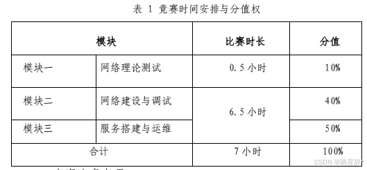
“网络建设与运维”竞赛共分 A.网络理论测试(从公布赛题模块 一中随机抽取选择题 70 道,判断题 30 道);B.网络建设与调试;C.服 务搭建与运维等三个模块。竞赛时间安排和分值权重见表 1。
二、竞赛注意事项
1.竞赛期间禁止携带和使用移动存储设备、计算器、通信工具及 参考资料。
2.请根据大赛所提供的竞赛环境,检查所列的硬件设备、软件清 单、材料清单是否齐全,计算机设备是否能正常使用。
3.在进行任何操作之前,请阅读每个部分的所有任务。各任务之 间可能存在一定关联。
4.操作过程中需要及时按照答题要求保存相关结果。竞赛结束后, 所有设备保持运行状态,评判以最后提交的成果为最终依据。
5.竞赛完成后,竞赛设备、软件和赛题请保留在座位上,禁止将 竞赛所用的所有物品(包括试卷等)带离赛场。
6.禁止在提交资料上填写与竞赛无关的标记,如违反规定,可视为0分。
模块二:网络建设与调试
任务描述:
某集团公司原在城市 A 成立了总公司,后在城市 B 成立了分公司, 又在城市 C 建立了办事处。集团设有产品、营销、法务、财务、人力 5 个部门,统一进行 IP 及业务资源的规划和分配,全网采用 OSPF、RIP、 ISIS、BGP 路由协议进行互联互通。 随着企业数字化转型工作进一步推进,为持续优化运营创新,充 分激活数据要素潜能,为社会创造更多价值,集团决定在总公司建立 两个数据中心,在某省建立异地灾备数据中心,以达到快速、可靠交 换数据,增强业务部署弹性的目的,完成向两地三中心整体战略架构 演进,更好的服务于公司客户。
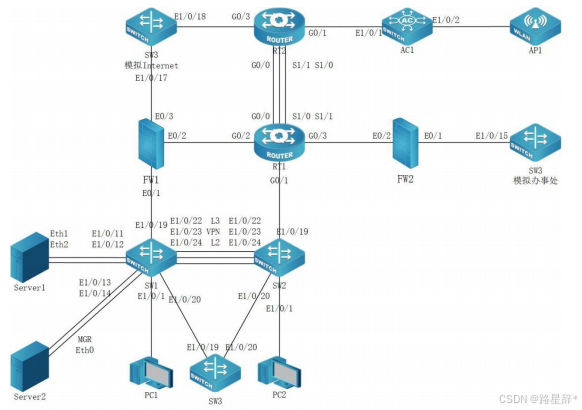
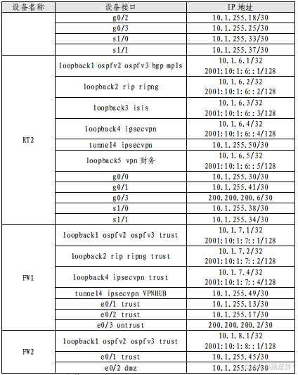
网络拓扑图及 IP 地址表:
1.网络拓扑图
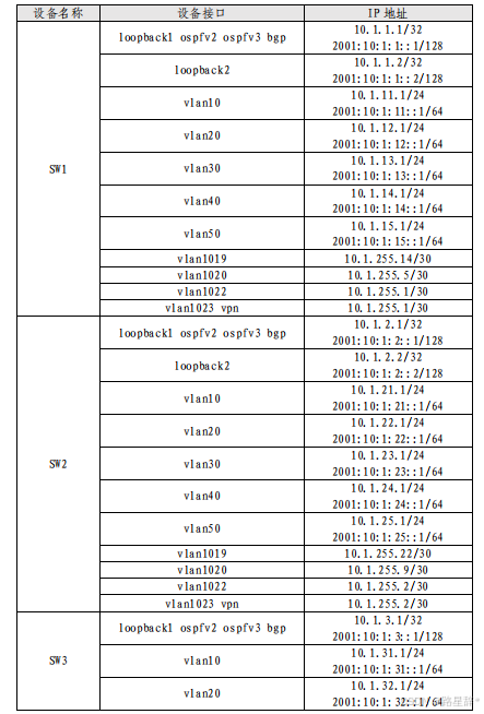
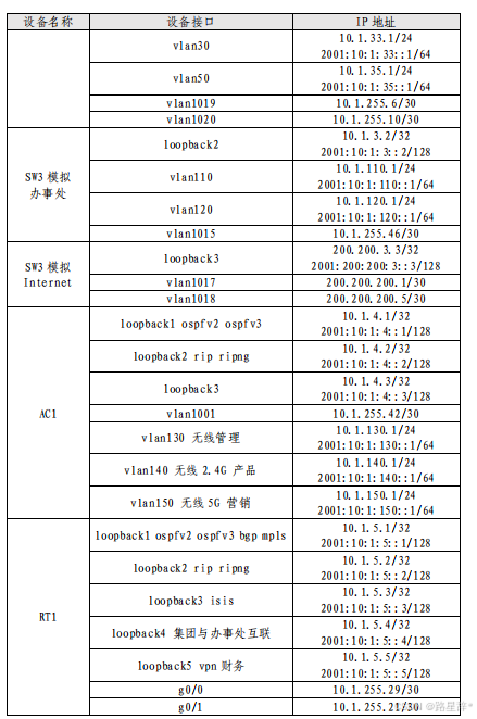
2.网络设备 IP 地址分配表
一、工程统筹
1.职业素养
(1)整理赛位,工具、设备归位,保持赛后整洁有序。
(2)无因选手原因导致设备损坏。
(3)恢复调试现场,保证网络和系统安全运行。
2.网络布线
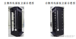
(1)机柜左侧布线面板编号 101;机柜右侧布线面板编号 102。
(2)面对信息底盒方向左侧为 1 端口、右侧为 2 端口。所有配线 架、模块按照 568B 标准端接。
(3)主配线区配线点与工作区配线点连线对应关系如下:
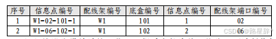
(4)铺设线缆并端接。截取 2 根适当长度的双绞线,两端制作标 签,穿过 PVC 线槽或线管。双绞线在机柜内部进行合理布线,并且通 过扎带合理固定。将 2 根双绞线的一端,端接在配线架相应端口,另 一端端接上 RJ45 模块,并且安装上信息点面板,并标注标签。
(5)跳线制作与测试。截取 2 根当长度的双绞线,端接水晶头, 所有网络跳线要求按 568B 标准制作,两端制作标签,连接网络信息点
和相应计算机。根据网络拓扑要求,截取适当长度和数量的双绞线, 端接水晶头,插入相应设备的相关端口上,实现 PC、信息点面板、配 线架、设备之间的连通(提示:可利用机柜上自带的设备进行通断测 试)。
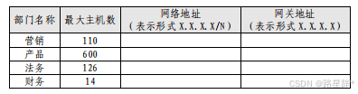
3.IP 规划
为了不断壮大集团业务经营范围,集团计划在上海成立办事处。通过调研,计划在上海办事处设立与 Internet 连接的 4 个业务部门, 每个业务部门的最大所需主机数如下表所示,要求从 10.1.10.100/19 主机地址所在网络第一个网段开始进行 IP 地址规划,IP 地址按照下表 依次往后顺延规划,网关地址取每个网段最后一个可用地址,请完成 下表 IP 地址规划。
二、交换配置
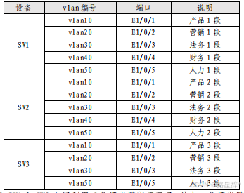
1.配置 vlan,SW1、SW2、SW3、AC1 的二层链路只允许相应 vlan 通过。
SW1:

vlan 10
 name cp1
!
vlan 20
 name yx1
!
vlan 30
 name fw1
!
vlan 40
 name cw1
!
vlan 50
 name rl1
!
Interface Ethernet1/0/1
 switchport access vlan 10
!
Interface Ethernet1/0/2
 switchport access vlan 20
!
Interface Ethernet1/0/3
 switchport access vlan 30
!
Interface Ethernet1/0/4
 switchport access vlan 40
!
Interface Ethernet1/0/5
 switchport access vlan 50
!
Interface Ethernet1/0/22
 switchport mode trunk
 switchport trunk allowed vlan 10;20;30;40;50   //设置二层链路只允许相应vlan通过

SW2:

vlan 10
 name cp2
!
vlan 20
 name yx2
!
vlan 30
 name fw2
!
vlan 40
 name cw2
!
vlan 50
 name rl2
!
Interface Ethernet1/0/1
 switchport access vlan 10
!
Interface Ethernet1/0/2
 switchport access vlan 20
!
Interface Ethernet1/0/3
 switchport access vlan 30
!
Interface Ethernet1/0/4
 switchport access vlan 40
!
Interface Ethernet1/0/5
 switchport access vlan 50
!
Interface Ethernet1/0/22
 switchport mode trunk
 switchport trunk allowed vlan 10;20;30;40;50   //设置二层链路只允许相应vlan通过

SW3:

vlan 10
 name cp3
!
vlan 20
 name yx3
!
vlan 30
 name fw3
!
vlan 50
 name rl3
!
Interface Ethernet1/0/1
 switchport access vlan 10
!
Interface Ethernet1/0/2
 switchport access vlan 20
!
Interface Ethernet1/0/3
 switchport access vlan 30
!
Interface Ethernet1/0/5
 switchport access vlan 50
2.SW1 和 SW2 之间利用三条裸光缆实现互通,其中一条裸光缆承载 三层 IP 业务、一条裸光缆承载 VPN 业务、一条裸光缆承载二层业务。 用相关技术分别实现财务 1 段、财务 2 段业务路由表与其它业务路由 表隔离,财务业务 VPN 实例名称为 Finance。承载二层业务的只有一条裸光缆通道,配置相关技术,方便后续链路扩容与冗余备份,编号为 1, 用 LACP 协议,SW1 为 active,SW2 为 passive;采用源、目的 IP 进行 实现流量负载分担。
SW1:

ip vrf Finance    //创建财务VPN实例
!
interface Vlan40   //财务1段
 ip vrf forwarding Finance   //将此接口绑定到vpn实例Finance中(注意:绑定完后IP地址会被清空)
 ip address 10.1.14.1 255.255.255.0
 ipv6 address 2001:10:1:14::1/64
!
interface Vlan1023        //承载VPN业务的VLAN
 ip vrf forwarding Finance    //将此接口绑定到vpn实例Finance中(注意:绑定完后之前配置的IP地址会被清空)
 ip address 10.1.255.1 255.255.255.252
!
port-group 1      //创建编号为1的端口聚合组
!
Interface Ethernet1/0/24  //进入承载二层业务的端口
 port-group 1 mode active   //绑定端口聚合组1并将模式设置成active
 lacp timeout short
!
load-balance dst-src-ip   //设置流量负载分担模式为源、目的IP

SW2:

ip vrf Finance    //创建财务VPN实例
!
interface Vlan40    //财务2段
 ip vrf forwarding Finance
 ip address 10.1.24.1 255.255.255.0
 ipv6 address 2001:10:1:24::1/64
!
interface Vlan1023
 ip vrf forwarding Finance
 ip address 10.1.255.2 255.255.255.252
!
port-group 1
!
Interface Ethernet1/0/24
 port-group 1 mode passive
 lacp timeout short
!
load-balance dst-src-ip
3.SW3 针对每个业务 VLAN 的第一个接口配置 Loopback 命令,模拟 接口 UP,方便后续业务验证与测试。
SW3:
interface ethernet 1/0/1-5   //进入每个业务VLAN的接口
loopback                  //配置接口为Loopback
!
4.将 SW3 模拟为 Internet 交换机,实现与集团其它业务路由表隔 离,Internet 路由表 VPN 实例名称为 Internet。将 SW3 模拟办事处交 换机,实现与集团其它业务路由表隔离,办事处路由表 VPN 实例名称 为 Office。
SW3:
ip vrf Office  //创建VPN实例 Office
!
ip vrf Internet  //创建VPN实例 Internet
!
interface Vlan110
 ip vrf forwarding Office   //将此接口绑定到vpn实例Office中(绑定完成后IP地址会被清空)
 ip address 10.1.110.1 255.255.255.0
 ipv6 address 2001:10:1:110::1/64
!
interface Vlan120
 ip vrf forwarding Office   //将此接口绑定到vpn实例Office中(绑定完成后IP地址会被清空)
 ip address 10.1.120.1 255.255.255.0
 ipv6 address 2001:10:1:12::1/64
!
interface Vlan1015
 ip vrf forwarding Office     //将此接口绑定到vpn实例Office中(绑定完IP地址会被清空)
 ip address 10.1.255.46 255.255.255.252
!
interface Vlan1017
 ip vrf forwarding Internet       //将此接口绑定到vpn实例Internet中(绑定完IP地址会被清空)
 ip address 200.200.200.1 255.255.255.252
!
interface Vlan1018
ip vrf forwarding Internet      //将此接口绑定到vpn实例Internet中(绑定完IP地址会被清空)
 ip address 200.200.200.5 255.255.255.252
!
interface Loopback2
 ip vrf forwarding Office   //将此接口绑定到vpn实例Office中(绑定完IP地址会被清空)
 ip address 10.1.3.2 255.255.255.255
 ipv6 address 2001:10:1:3::2/32
!
interface Loopback3
 ip vrf forwarding Internet   //将此接口绑定到vpn实例Internet中(绑定完IP地址会被清空)
 ip address 200.200.3.3 255.255.255.255
 ipv6 address 2001:200:200:3::3/128
5.SW1 配置 SNMP,引擎 id 分别为 1000;创建组 GroupSkills,采 用最高安全级别,配置组的读、写视图分别为:Skills_R、Skills_W; 创建认证用户为 UserSkills,采用 aes 算法进行加密,密钥为 Key-1122, 哈希算法为 sha,密钥为 Key-1122;当设备有异常时,需要用本地的 环回地址 loopback1 发送 v3 Trap 消息至集团网管服务器 10.1.15.120、 2001:10:1:15::120,采用最高安全级别;当法务部门对应的用户接口 发生 UP DOWN 事件时禁止发送 trap 消息至上述集团网管服务器。
SW1:
snmp-server enable  //开启SNMP功能
snmp-server trap-source 10.1.1.1  // LoopBack1的IPv4地址
snmp-server trap-source 2001:10:1:1::1  // LoopBack1的IPv6地址
snmp-server engineid 1000   //设置引擎id为1000
snmp-server user UserSkills GroupSkills authPriv aes Key-122 auth sha Key-122 //采用 aes 算法进行加密,哈希算法为 sha,设置密码为Key-122
snmp-server group GroupSkills authpriv read Skills_R write Skills_W  //创建组Groups,配置组的读、写视图
snmp-server host 2001:10:1:15::120 v3 authpriv UserSkills //设置接收端(网管服务器地址,配置最高安全级别v3)
snmp-server host 10.1.15.120 v3 authpriv UserSkills  //设置接收端地址
snmp-server enable traps   //开启SNMP traps功能
!

接口发生UP DOWN事件时禁止发送trap消息至上述集团网管服务器:

Interface Ethernet1/0/3  //法务1
 no switchport updown notification enable
6.对 SW1 与 FW1 互连流量镜像到 SW1 E1/0/1,会话列表为 1。
SW1:
monitor session 1 source interface ethernet 1/0/19 both //配置源端口
monitor session 1 destination interface ethernet 1/0/1  //配置目的端口
7.SW1 和 SW2 E1/0/21-28 启用单向链路故障检测,当发生该故障 时,端口标记为 errdisable 状态,自动关闭端口,经过 1 分钟后,端 口自动重启;发送 Hello 报文时间间隔为 15s。
SW1:

uldp enable //开启uldp 功能
uldp recovery-time 60  //设置端口重启时间为1分钟
uldp hello-interval 15   //设置发送Hello报文的时间间隔为15s
uldp aggressive-mode  //发生故障时,端口标记为errdisable

SW1 E1/0/21-28 启用单向链路故障检测:

interface ethernet 1/0/21-28
uldp enable
uldp aggressive-mode

SW2:
uldp enable
uldp recovery-time 60
uldp hello-interval 15
uldp aggressive-mode

SW2 E1/0/21-28 启用单向链路故障检测:

interface ethernet 1/0/21-28
uldp enable
uldp aggressive-mode
8.SW1 和 SW2 所有端口启用链路层发现协议,更新报文发送时间间 隔为 20s,老化时间乘法器值为 5,Trap 报文发送间隔为 10s,配置三 条裸光缆端口使能 Trap 功能。
SW1:
!
lldp enable  //开启lldp功能
lldp msgTxHold 5  //设置老化时间乘法器值为 5
lldp tx-interval 20  //设置更新报文发送时间间隔为 20s
lldp notification interval 10   //设置Trap 报文发送间隔为 10s
!
SW1 所有端口启用链路层发现协议:

interface ethernet 1/0/1-28
lldp enable
!
配置三条裸光缆端口使能 Trap 功能:

interface ethernet 1/0/22-24
lldp trap enable

SW2:

lldp enable  //开启lldp功能
lldp msgTxHold 5  //设置老化时间乘法器值为 5
lldp tx-interval 20  //设置更新报文发送时间间隔为 20s
lldp notification interval 10   //设置Trap 报文发送间隔为 10s
!
SW2 所有端口启用链路层发现协议:

interface ethernet 1/0/1-28
lldp enable
!
配置三条裸光缆端口使能 Trap 功能:

interface ethernet 1/0/22-24
lldp trap enable
三、路由调试
1.启用所有设备的 ssh 服务,防火墙用户名 admin,明文密码 Key-1122,其余设备用户名和明文密码均为 admin。
注:所有设备的主机名都是 hostname+主机名,所有设备的用户名和密码都默认是admin,不用配置

SW1、2、3、AC:
ssh-server enable  //开启ssh 功能

RT1、2:
ip sshd enable      //开启ssh 功能

FW1、2:
admin user "admin"  //设置用户名为admin
  password Key-1122  //配置明文密码
  access ssh  //开启ssh功能
2.配置所有设备的时区为 GMT+08:00,调整 SW1 时间为实际时间, SW1 配置为 ntp server,其他设备用 SW1 loopback1 ipv4 地址作为 ntp server 地址,ntp client 请求报文时间间隔 1 分钟。
SW1:
ntp enable  //开启ntp功能
clock timezone GMT add 8 0  //设置时区为GMT+08:00
ntp-service refclock-master 1  //设置SW1作为NTP主时钟,提供同步时间

SW2、3、AC1:
ntp enable   //开启ntp功能
clock timezone GMT add 8 0   //设置时区为GMT+08:00
ntp syn-interval 60     //设置ntp client 请求报文时间间隔为 1 分钟
ntp server 10.1.1.1    //将SW1 loopback1 ipv4 地址设为 ntp server 地址

RT1、2:
time-zone GMT 8 0  //设置时区
ntp query-interval 60   //设置ntp client 请求报文时间间隔为 1 分钟
ntp server 10.1.1.1    //将SW1 loopback1 ipv4 地址设为 ntp server 地址


FW1、2:
ntp enable   //开启ntp功能
clock zone GMT 8 0  //设置时区
ntp query-interval 2  //设置ntp client 请求报文时间间隔为 1 分钟
ntp server 10.1.1.1    //将SW1 loopback1 ipv4 地址设为 ntp server 地址
3.配置接口 ipv4 地址和 ipv6 地址,互联接口 ipv6 地址用本地链 路地址。
注:互联接口是指直连接口;交换机与AC默认开启ipv6功能,不用配置;
所以只用在路由器,防火墙上配置

RT :
ipv6 unicast-routing 开启IPV6本地链路地址

进入接口:
ipv6 enable

FW:

进入接口:
ipv6 enable
4.SW2 配置 DHCPv4 和 DHCPv6,分别为总公司产品 1 段、总公司产 品 2 段、分公司 Vlan130、分公司 Vlan140 和分公司 Vlan150 分配地址。 IPv4 地 址 池 名 称 分 别 为 Poolv4-Vlan11 、 Poolv4-Vlan21 、 Poolv4-Vlan130、Poolv4-Vlan140、Poolv4-Vlan150,排除网关,DNS 为 10.1.210.101 和 10.1.220.101 。 IPv6 地 址 池 名 称 分 别 为 Poolv6-Vlan11、Poolv6-Vlan21、Poolv6-Vlan130、Poolv6-Vlan140、 Poolv6-Vlan150,IPv6 地址池用网络前缀表示,排除网关,DNS 为 2400:3200::1。PC1 保留地址 10.1.11.9 和 2001:10:1:11::9,PC2 保 留地址 10.1.21.9 和 2001:10:1:21::9,AP1 保留地址 10.1.130.9 和 2001:10:1:130::9。SW1、AC1 中继地址为 SW2 Loopback1 地址,SW1 启用 DHCPv4 和 DHCPv6 snooping,如果 E1/0/1 连接 dhcpv4 服务器, 则关闭该端口,恢复时间为 10 分钟。
SW1:
service dhcp  //开启DHCP功能
!
ip forward-protocol udp bootps   //启动dhcp中继转发功能
!
ip dhcp snooping enable   //启动dhcpv4 snooping功能
!
service dhcpv6  //开启DHCPv6功能
!
savi enable
 savi ipv6 dhcp-only enable  //开启DHCPv6 snooping功能
!
Interface Ethernet1/0/1
 ip dhcp snooping action shutdown recovery 600  //设置恢复时间为10分钟
!
interface Vlan10
 no ipv6 nd suppress-ra    //开启路由通告功能
 ipv6 nd managed-config-flag  //地址配置时使用有状态的dhcpv6协议
 ipv6 nd other-config-flag    //地址配置时使用无状态的dhcpv6协议
 ip helper-address 10.1.2.1   //设置dhcpv4中继目标
 ipv6 dhcp relay destination 2001:10:1:2::1  //设置dhcpv6中继目标


SW2:
service dhcp   //开启DHCP功能
!
配置ipv4地址池,保留地址,配置网关:
ip dhcp pool Poolv4-Vlan11
 network-address 10.1.11.0 255.255.255.0
 default-router 10.1.11.1
 dns-server 10.1.210.101 10.1.220.101  //配置DNS
!
ip dhcp pool Poolv4-Vlan21
 network-address 10.1.21.0 255.255.255.0
 default-router 10.1.21.1
 dns-server 10.1.210.101 10.1.220.101   //配置DNS
!
ip dhcp pool Poolv4-Vlan130
 network-address 10.1.130.0 255.255.255.0
 default-router 10.1.130.1
 dns-server 10.1.210.101 10.1.220.101  //配置DNS
!
ip dhcp pool Poolv4-Vlan140
 network-address 10.1.140.0 255.255.255.0
 default-router 10.1.140.1
 dns-server 10.1.210.101 10.1.220.101   //配置DNS
!
ip dhcp pool Poolva-Vlan150
 network-address 10.1.150.0 255.255.255.0
 default-router 10.1.150.1
 dns-server 10.1.210.1 10.1.220.1       //配置DNS
!
ip dhcp pool AP1
 host 10.1.130.9 255.255.255.0
 hardware-address C0-18-03-88-9F-94   //绑定mac地址
!
ip dhcp pool PC1
 host 110.1.11.9 255.255.255.0
 hardware-address 98-0E-2B-AB-83-F1   //绑定mac地址
!
ip dhcp pool PC2
 host 10.1.21.9 255.255.255.0
 hardware-address 00-03-0F-D9-CD-C0   //绑定mac地址
!
service dhcpv6   //开启DHCPv6功能
!
配置ipv6地址池,保留地址,配置网关:
ipv6 dhcp pool Poolv6-Vlan150
 network-address 2001:10:1:150::1 64
 excluded-address 2001:10:1:150::1
 dns-server 2400:3200::1          //配置DNS
!
ipv6 dhcp pool Poolv6-Vlan140
 network-address 2001:10:1:140::1 64
 excluded-address 2001:10:1:140::1
 dns-server 2400:3200::1         //配置DNS
!
ipv6 dhcp pool Poolv6-Vlan130
 network-address 2001:10:1:130::1 64
 static-binding 2001:10:1:130::1 c0-18-03-88-9f-94      //保留地址并且绑定mac地址
 excluded-address 2001:10:1:130::1
 dns-server 2400:3200::1         //配置DNS
!
ipv6 dhcp pool Poolv6-Vlan21
 network-address 2001:10:1:21::1 64
 static-binding 2001:10:1:21::1 00-03-0f-d9-cd-c0     //保留地址并且绑定mac地址
 excluded-address 2001:10:1:21::1
 dns-server 2400:3200::1        //配置DNS
!
ipv6 dhcp pool Poolv6-Vlan11
 network-address 2001:10:1:11::1 64
 static-binding 2001:10:1:11::1 98-0e-2b-ab-83-f1   //保留地址并且绑定mac地址
 excluded-address 2001:10:1:11::1//配置DNS
 dns-server 2400:3200::1

AC1:
service dhcp        //开启dhcp功能
!
ip forward-protocol udp bootps    //启动dhcp中继转发功能
!
service dhcpv6   //开启dhcpv6功能
!
interface Vlan130
 no ipv6 nd suppress-ra    //开启路由通告功能
 ipv6 nd managed-config-flag  //地址配置时使用有状态的dhcpv6协议
 ipv6 nd other-config-flag    //地址配置时使用无状态的dhcpv6协议
 ip helper-address 10.1.2.1   //设置dhcpv4中继目标
 ipv6 dhcp relay destination 2001:10:1:2::1  //设置dhcpv6中继目标
!
interface Vlan140
 no ipv6 nd suppress-ra
 ipv6 nd managed-config-flag
 ipv6 nd other-config-flag
 ip helper-address 10.1.2.1
 ipv6 dhcp relay destination 2001:10:13:2::1
!
interface Vlan150
 no ipv6 nd suppress-ra
 ipv6 nd managed-config-flag
 ipv6 nd other-config-flag
 ip helper-address 10.1.2.1
 ipv6 dhcp relay destination 2001:10:13:2::1
5.SW1、SW2、SW3、RT1 以太链路、RT2 以太链路、FW1、FW2、AC1 之间运行 OSPFv2 和 OSPFv3 协议(路由模式发布网络用接口地址,BGP 协议除外)。
(1)SW1、SW2、SW3、RT1、RT2、FW1 之间 OSPFv2 和 OSPFv3 协议, 进程 1,区域 0,分别发布 loopback1 地址路由和产品路由,FW1 通告 type1 默认路由。
SW1:
router ospf 1
 ospf router-id 10.1.1.1
 network 10.1.1.1/32 area 0  //发布Loopback1地址路由
 network 10.1.11.0/24 area 0   //发布产品地址路由
 宣告同一网段的直连路由:
network 10.1.255.0/30 area 0
 network 10.1.255.4/30 area 0
 network 10.1.255.12/30 area 0

进入题目中相应的VLAN和Loopback,宣告ipv6网段:
interface Vlan10
 ipv6 router ospf area 0 tag 1
!
interface Vlan1019
 ipv6 router ospf area 0 tag 1
!
interface Vlan1020
 ipv6 router ospf area 0 tag 1
!
interface Vlan1022
 ipv6 router ospf area 0 tag 1
!
interface Loopback1
 ipv6 router ospf area 0 tag 1


SW2:
router ospf 1
 ospf router-id 10.1.2.1
 network 10.1.2.1/32 area 0      //发布Loopback1地址路由
 network 10.1.21.0/24 area 0       //发布产品地址路由
宣告同一网段的直连路由:
 network 10.1.255.0/30 area 0
 network 10.1.255.8/30 area 0
 network 10.1.255.20/30 area 0

进入题目中相应的VLAN和Loopback,宣告ipv6网段:
interface Vlan10
 ipv6 router ospf area 0 tag 1
!
interface Vlan1019
 ipv6 router ospf area 0 tag 1
!
interface Vlan1020
 ipv6 router ospf area 0 tag 1
!
interface Vlan1022
 ipv6 router ospf area 0 tag 1
!
interface Loopback1
 ipv6 router ospf area 0 tag 1

SW3:
router ospf 1
 ospf router-id 10.1.3.1
 network 10.1.3.1/32 area 0     //发布Loopback1地址路由
 network 10.1.255.4/30 area 0   //发布产品地址路由
宣告同一网段的直连路由:
network 10.1.255.8/30 area 0

进入题目中相应的VLAN和Loopback,宣告ipv6网段:
interface Vlan10
 ipv6 router ospf area 0 tag 1
!
interface Vlan1019
 ipv6 router ospf area 0 tag 1
!
interface Vlan1020
 ipv6 router ospf area 0 tag 1
!
interface Loopback1
 ipv6 router ospf area 0 tag 1

RT1:
router ospf 1
 router-id 10.1.5.1
 network 10.1.5.1 255.255.255.255 area 0   //发布Loopback1地址路由
 宣告同一网段的直连路由:
network 10.1.255.28 255.255.255.252 area 0
 network 10.1.255.20 255.255.255.252 area 0
 network 10.1.255.16 255.255.255.252 area 0

进入题目中相应的直连端口和Loopback,宣告ipv6网段:
ipv6 unicast-routing  //必须先开启ipv6单播路由,才能做下一步
!
router ospfv3 1
 router-id 10.1.5.1
!
interface Loopback1
 ipv6 ospf 1 area 0
!
interface GigaEthernet0/0
 ipv6 ospf 1 area 0
!
interface GigaEthernet0/1
 ipv6 ospf 1 area 0
!
interface GigaEthernet0/2
 ipv6 ospf 1 area 0

RT2:
router ospf 1
 router-id 10.1.6.1
 network 10.1.6.1 255.255.255.255 area 0  //发布Loopback1地址路由
宣告同一网段的直连路由:
network 10.1.255.28 255.255.255.252 area 0

进入题目中相应的直连端口和Loopback,宣告ipv6网段:
ipv6 unicast-routing   //必须先开启ipv6单播路由,才能做下一步
!
router ospfv3 1
 router-id 10.1.6.1
!
interface Loopback1
 ipv6 ospf 1 area 0
!
interface GigaEthernet0/0
 ipv6 ospf 1 area 0

FW1:
  router ospf 1
    router-id 10.1.7.1
    default-information originate always type 1  //FW1通告type1默认路由
    network 10.1.7.1/32 area 0   //发布Loopback1地址路由
  宣告同一网段的直连路由:
    network 10.1.255.12/30 area 0
    network 10.1.255.16/30 area 0

 进入题目中相应的直连端口和Loopback,宣告ipv6网段:
 ipv6 router ospf 1
   router-id 10.13.7.1
   !
   interface loopback1
    ipv6 enable
    ipv6 ospf 1 area 0
   !
    interface ethernet0/1
    ipv6 enable
    ipv6 ospf 1 area 0
   !
   interface ethernet0/2
    ipv6 enable
    ipv6 ospf 1 area 0
(2)RT2 与 AC1 之间运行 OSPFv2 协议,进程 1,nssa no-summary 区域 1;AC1 发布loopback1 地址路由、产品和营销路由,用 prefix-list 重发布 loopback3。
RT2:
router ospf 1
router-id 10.1.6.1
network 10.1.255.40 255.255.255.252 area 1    //宣告RT2与AC1的直连路由
area 1 nssa no-summary   //设置nssa no-summary区域 1

AC1:

ip prefix-list AC1-Loopback3 seq 5 permit 10.1.4.3/32   //创建前缀列表
!
route-map AC1-Loopback3 permit 10      //创建route-map,调用前缀列表
 match ip address prefix-list AC1-Loopback3
!
router ospf 1
router-id 10.13.4.1
area 1 nssa no-summary             //设置nssa no-summary区域 1
network 10.1.4.1/32 area 1       //宣告Loopback1地址路由
network 10.1.140.1/24 area 1    //宣告产品路由
network 10.1.150.1/24 area 1   //宣告营销路由
network 10.1.255.40/30 area 1  //宣告AC1与RT2的直连路由
redistribute connected route-map AC-Loopback3  //调用route-map重发布Loopback3
(3)RT2 与 AC1 之间运行 OSPFv3 协议,进程 1,stub no-summary 区域 1;AC1 发布 loopback1 地址路由、产品和营销。
RT2:
ipv6 unicast-routing  //必须先开启ipv6单播路由,才能做下一步
!
router ospfv3 1
router-id 10.1.6.1
 area 1 stub no-summary  //设置stub no-summary 区域 1

进入题目中相应的直连接口,宣告ipv6网段:
interface GigaEthernet0/1
 ipv6 enable
 ipv6 ospf 1 area 1


AC1:
router ipv6 ospf 1
 router-id 10.1.4.1
 area 1 stub no-summary  //设置stub no-summary 区域 1

进入题目中相应的VLAN和Loopback,宣告ipv6网段:
interface Vlan140
 ipv6 router ospf area 1 tag 1
!
interface Vlan150
 ipv6 router ospf area 1 tag 1
!
interface Vlan1001
 ipv6 router ospf area 1 tag 1
!
interface Loopback1
 ipv6 router ospf area 1 tag 1
(4)SW3 模拟办事处产品和营销接口配置为 loopback,模拟接口 up。SW3 模拟办事处与 FW2 之间运行 OSPFv2 协议,进程 2,区域 2,SW3 模拟办事处发布 loopback2、产品和营销。SW3 模拟办事处配置 ipv6 默认路由;FW2 分别配置到 SW3 模拟办事处 loopback2、产品和营销的 ipv6 明细静态路由,FW2 重发布静态路由到 OSPFv3 协议。
SW3:
Interface Ethernet1/0/11  //模拟办事处产品接口
 loopback
!
Interface Ethernet1/0/12  //模拟办事处营销接口
 loopback
!
router ospf 2 vrf Office
 ospf router-id 10.1.3.2
 network 10.1.3.2/32 area 2  //发布Loopback2地址路由
 network 10.1.110.0/24 area 2  //发布产品路由
 network 10.1.120.0/24 area 2  //发布营销路由
 network 10.1.255.44/30 area 2  //发布SW3模拟办事处到FW2的直连路由
!
router ipv6 ospf 2
 router-id 10.1.3.2

进入题目中相应的VLAN和Loopback,宣告ipv6网段:
interface Vlan110
 ip vrf forwarding Office
 ipv6 router ospf area 2 tag 2
!
interface Vlan120
 ip vrf forwarding Office
 ipv6 router ospf area 2 tag 2
!
interface Vlan1015
 ip vrf forwarding Office
 ipv6 router ospf area 2 tag 2
!
interface Loopback2
 ip vrf forwarding Office
 ipv6 router ospf area 2 tag 2

ipv6 route ::/0 :: vlan1015   //配置ipv6默认路由

FW2:
  router ospf 2
    router-id 10.1.8.1
    network 10.1.8.1/32 area 2         //发布Loopback1地址路由
    network 10.1.255.44/30 area 2     //发布FW2到SW3模拟办事处的地址路由
!
router ipv6 ospf 2
  router-id 10.1.8.1

进入题目中相应的直连接口和Loopback,宣告ipv6网段:
interface loopback2
    ipv6 enable
    ipv6 ospf 1 area 2
!
Interface Ethernet0/1
    ipv6 enable
    ipv6 ospf 1 area 2
!
ipv6 route 2001:10:1:3::2/128 ethernet0/1   // 配置到SW3模拟办事处loopback2的静态路由
ipv6 route 2001:10:1:110::0/64 ethernet0/1   //配置到SW3模拟办事处产品的静态路由
ipv6 route 2001:10:1:120::0/64 ethernet0/1   //配置到SW3模拟办事处营销的静态路由
!

router ipv6 ospf 2
redistribute  static     //FW2重发布静态路由
(5)RT1、FW2 之间 OSPFv2 和 OSPFv3 协议,进程 2,区域 2;RT1 发布 loopback4 路由,向该区域通告 type1 默认路由;FW2 发布 loopback1 路由,FW2 禁止学习到集团和分公司的所有路由。RT1 用 prefix-list 匹配 FW2 loopback1 路由、SW3 模拟办事处 loopback2 和 产品路由、RT1 与 FW2 直连 ipv4 路由,将这些路由重发布到区域 0。
RT1:

router ospf 2
 router-id 10.1.5.4
 network 10.1.5.4 255.255.255.255 area 2   //发布Loopback4地址路由
 network 10.1.255.24 255.255.255.252 area 2   //发布RT1与FW2的直连路由
 default-information originate always metric-type 1    //通告type1默认路由

RT1用ip prefix-list 匹配题目中的地址路由:
ip prefix-list FW2-Loopback1 seq 5 permit 10.1.8.1/32
route-map FW2-Loopback1 10 permit
 match ip address prefix-list FW2-Loopback1
!
ip prefix-list SW3-CP seq 10 permit 10.1.110.0/30
route-map SW3-CP 10 permit
 match ip address prefix-list SW3-CP
!
ip prefix-list SW3-Loopback2 seq 15 permit 10.1.3.2/32
route-map SW3-Loopback2 10 permit
 match ip address prefix-list SW3-Loopback2
!
ip prefix-list RT1-FW2-IPv4 seq 20 permit 10.1.255.24/30
route-map RT1-FW2-IPv4 10 permit
 match ip address prefix-list RT1-FW2-IPv4

进入题目中相应的直连接口和Loopback,宣告ipv6网段:
ipv6 unicast-routing  //开启ipv6 单播路由
!
router ospfv3 2
 router-id 10.1.5.4
!
interface Loopback1
 ipv6 ospf 2 area 2
!
interface GigaEthernet0/3
 ipv6 ospf 2 area 2

将以上所匹配的地址路由重发布到区域0中:
router ospf 1
redistribute connect route-map FW2-Loopback1
redistribute connect route-map SW3-Loopback2
redistribute connect route-map SW3-CP
redistribute connect route-map RT1-FW2-IPv4


FW2:
  router ospf 2
    router-id 10.1.8.1
    network 10.1.8.1/32 area 2   //发布Loopback1地址路由
    network 10.1.255.24/30 area 2   //发布FW2与RT1的直连路由

进入题目中相应的直连接口和Loopback,宣告ipv6网段:
ipv6 router ospf 2
  router-id 10.1.8.1
!
interface loopback1
 ipv6 enable
 ipv6 ospf 2 area 2
!
interface ethernet0/2
 ipv6 enable
 ipv6 ospf 2 area 2

FW2 禁止学习到集团和分公司的所有路由:
ip prefix-list zx seq 5 permit 10.1.8.1/32
ip prefix-list zx seq 10 permit 10.1.3.2/32
ip prefix-list zx seq 15 permit 10.1.110.0/30
ip prefix-list zx seq 20 permit 10.1.255.24/30
!
route-map zx 10 permit
 match ip address prefix-list zx

router ospf 1
 redistribute static route-map zx
(6)修改 ospf cost 为 100,实现 SW1 分别与 RT2、FW2 之间 ipv4 和 ipv6 互访流量优先通过 SW1_SW2_RT1 链路转发,SW2 访问 Internet ipv4 和 ipv6 流量优先通过 SW2_SW1_FW1 链路转发。
RT1:
interface GigaEthernet0/2
 ip ospf cost 100         //设置ospf cost为100
 ipv6 ospf cost 100      //设置ipv6 ospf cost为100


FW2:
interface ethernet0/2
 ip ospf cost 100      //设置ospf cost为100
 ipv6 ospf cost 100   //设置ipv6 ospf cost为100
6.RT1 串行链路、RT2 串行链路、FW1、AC1 之间分别运行 RIP 和 RIPng 协议,FW1、RT1、RT2 的 RIP 和 RIPng 发布 loopback2 地址路由, AC1 RIP 发布 loopback2 地址路由,AC1 RIPng 采用 route-map 匹配 prefix-list 重发布 loopback2 地址路由。RT1 配置 offset 值为 3 的 路由策略,实现 RT1-S1/0_RT2-S1/1 为主链路,RT1-S1/1_RT2-S1/0 为备份链路,ipv4 的 ACL 名称为AclRIP,ipv6 的ACL 名称为 AclRIPng。 RT1 的 S1/0 与 RT2 的 S1/1 之间采用 chap 双向认证,用户名为对端设 备名称,密码为 Key-1122。
RT1:

aaa authentication login default none
aaa authentication enable default none //取消登录认证
aaa authentication ppp default local  //PPP认证方式本地
!
username RT2 password 0 Key-1122  //设置用户名为对端设备名称,密码为Key-1122

interface Serial1/0
 encapsulation ppp      //封装ppp
 ppp authentication chap   //验证方式为chap
 ppp chap hostname RT1
 ppp chap password 0 Key-1122    //配置验证密码
 ipv6 enable
!
interface Serial1/1
 encapsulation ppp
 ipv6 enable

创建ipv4和ipv6访问控制列表:
ip access-list standard AclRIP  //配置名称为AclRIP的ipv4 ACL
 permit any  sequence 10
!
 ipv6 unicast-routing           //开启ipv6单播路由
!
ipv6 access-list AclRIPng       //配置名称为AclRIPng的ipv6 ACL
 permit ipv6 any any sequence 10
!
router rip 1
 offset Serial1/1 in AclRIP 3   // 配置offset值为3
 offset Serial1/1 out AclRIP 3  // 配置offset值为3
!
router ripng 1
 offset Serial1/1 in AclRIPng 3    // 配置offset值为3
 offset Serial1/1 out AclRIPng 3   // 配置offset值为3
!
interface Loopback2
 ipv6 enable
 ip rip 1 enable
 ipv6 rip 1 enable
!
interface GigaEthernet0/2    //为了互通与FW1,RT1与FW1的直连端口配置rip
 ipv6 enable
 ip rip 1 enable
 ipv6 rip 1 enable
!
interface Serial1/0
 ipv6 enable
 ip rip 1 enable
 ipv6 rip 1 enable
!
interface Serial1/1
 ipv6 enable
 ip rip 1 enable
 ipv6 rip 1 enable


RT2:

aaa authentication login default none
aaa authentication enable default none //取消登录认证
aaa authentication ppp default local  //PPP认证方式本地
!
username RT1 password 0 Key-1122  //设置用户名为对端设备名称,密码为Key-1122

interface Serial1/0
 encapsulation ppp      //封装ppp
 ppp authentication chap   //验证方式为chap
 ppp chap hostname RT2
 ppp chap password 0 Key-1122    //配置验证密码
 ipv6 enable
!
interface Serial1/1
 encapsulation ppp
 ipv6 enable
!
router rip 1
!
ipv6 unicast-routing           //开启ipv6单播路由
!
router ripng 1
!
interface Loopback2
 ipv6 enable
 ip rip 1 enable
 ipv6 rip 1 enable
!
interface GigaEthernet0/1       //为了互通与AC1,RT2与AC1的直连端口配置rip
 ipv6 enable
 ip rip 1 enable
 ipv6 rip 1 enable
!
interface Serial1/0
 ipv6 enable
 ip rip 1 enable
 ipv6 rip 1 enable
!
interface Serial1/1
 ipv6 enable
 ip rip 1 enable
 ipv6 rip 1 enable

FW1:
  router rip
  network 10.13.7.2/32
  network 10.13.255.16/30
!
ipv6 router rip
network ethernet 0/2  //ipv6 宣告时用接口名称
network Loopback2


AC1:
ip prefix-list AC1-Loopback2 seq 5 permit 10.13.4.2/32   //创建前缀列表
!
route-map AC1-Loopback2 permit 10      //创建route-map,调用前缀列表
 match ip address prefix-list AC1-Loopback2
!
router rip
network 10.13.4.2/32
network 10.13.255.40/30
redistribute connected route-map AC1-Loopback2  //调用route-map重发布Loopback2
!
router ipv6 rip
!
7.RT1 以太链路、RT2 以太链路之间运行 ISIS 协议,进程 1,分别 实现 loopback3 之间 ipv4 互通和 ipv6 互通。RT1、RT2 的 NET 分别为 10.0000.0000.0001.00 、 10.0000.0000.0002.00 , 路 由 器 类 型 是 Level-2,接口网络类型为点到点。配置域 md5 认证和接口 md5 认证, 密码均为 Key-1122。
RT1:
router isis 1
 is-type level-2    //配置路由器类型为Level-2
 authentication mode md5       //配置域md5 认证
 authentication key 0 Key-1122    //密码为Key-1122
 net 10.0000.0000.0001.00  //配置NET为10.0000.0000.0001.00
!
interface Loopback3
 ipv6 enable
 ip router isis 1
 ipv6 router isis 1
!
interface GigaEthernet0/0
 ipv6 enable
 ip router isis 1
 ipv6 router isis 1
 isis network point-to-point  //配置接口网络类型为点到点
 isis circuit-type level-2   //配置路由器类型为Level-2
 isis authentication mode md5    //配置接口md5 认证
 isis authentication key 0 Key-1122    //密码为Key-1122
!
RT2:
router isis 1
 is-type level-2    //配置路由器类型为Level-2
 authentication mode md5       //配置域md5 认证
 authentication key 0 Key-1122    //密码为Key-1122
 net 10.0000.0000.0002.00  //配置NET为10.0000.0000.0002.00
!
interface Loopback3
 ipv6 enable
 ip router isis 1
 ipv6 router isis 1
!
interface GigaEthernet0/0
 ipv6 enable
 ip router isis 1
 ipv6 router isis 1
 isis network point-to-point  //配置接口网络类型为点到点
 isis circuit-type level-2   //配置路由器类型为Level-2
 isis authentication mode md5    //配置接口md5 认证
 isis authentication key 0 Key-1122    //密码为Key-1122
!
8.RT2 配置 ipv4 nat,实现 AC1 ipv4 产品用 RT2 外网接口 ipv4 地址访问 Internet。RT2 配置 nat64,实现 AC1 ipv6 产品用 RT2 外网 接口 ipv4 地址访问 Internet,ipv4 地址转 ipv6 地址前缀为 64:ff9b::/96。
RT2:
ip route default 200.200.200.5  //设置默认路由将所有未指明目的地的流量(即默认路由)转发到指定的下一跳地址,以便能成功访问外网.
!
interface GigaEthernet0/1
ip nat inside
ipv6 nat   //接口启动ipv6转换
!
interface GigaEthernet0/2
ip nat outside
ipv6 nat  //接口启动ipv6转换
!
ip access-list standard ACL-NAT     //约定NAT4转换规则
 permit any  sequence 10
!
ipv6 access-list ACL-NAT64        //约定NAT64转换规则
 permit ipv6 2001:10:13:140::/64 any sequence 10
!
ip nat inside source list ACL-NAT interface GigaEthernet0/3  //ipv4转换规则
!
ipv6 nat v6v4 source list ACL-NAT64 interface GigaEthernet0/3   //ipv6转换规则
ipv6 nat prefix 64:FF9B::/96 v4-mapped ACL-NAT64   //设置ipv4 地址转 ipv6 地址前缀
9.SW1、SW2、SW3、RT1、RT2 之间运行 BGP 协议,SW1、SW2、RT1 AS 号 65001、RT2 AS 号 65002、SW3 AS 号 65003。
(1)SW1、SW2、SW3、RT1、RT2 之间通过 loopback1 建立 ipv4 和 ipv6 BGP 邻居。SW1 和 SW2 之间财务通过 loopback2 建立 ipv4 BGP 邻居,SW1 和 SW2 的 loopback2 互通采用静态路由。
(2)SW1、SW2、SW3、RT2 分别只发布营销、法务、财务、人力等 ipv4 和 ipv6 路由;RT1 发布办事处营销 ipv4 和 ipv6 路由到 BGP。
SW1:
router bgp 65001   //启用BGP,as为65001
 bgp router-id 10.1.1.1   //指定router-id
 network 10.1.12.0/24    //SW1发布营销路由
 network 10.1.13.0/24   //SW1发布法务路由
 network 10.1.15.0/24  //SW1发布人力路由
 neighbor 10.1.2.1 remote-as 65001  //建立ipv4邻居关系
 neighbor 10.1.2.1 update-source Loopback1    //指定ipv4更新源为Loopback1
 neighbor 10.1.2.1 next-hop-self   //与IBGP指定下一跳配置
 neighbor 10.1.3.1 remote-as 65003
 neighbor 10.1.3.1 ebgp-multihop 255  //与ebgp建立IPv4邻居关系
 neighbor 10.1.3.1 update-source Loopback1
 neighbor 2001:10:1:2::1 remote-as 65001  //建立ipv6邻居关系
 neighbor 2001:10:1:2::1 update-source Loopback1   //指定ipv6更新源为Loopback1
 no neighbor 2001:10:1:2::1 activate   //在ipv4中取消IPv6中激活
  neighbor 2001:10:1:3::1 remote-as 65001
 neighbor 2001:10:1:3::1 update-source Loopback1  //指定ipv6更新源为Loopback1
 no neighbor 2001:10:1:3::1 activate   //在ipv4中取消IPv6中激活
 address-family ipv6 unicast
 network 2001:10:1:12::/64   //SW1发布营销ipv6路由
 network 2001:10:1:13::/64   //SW1发布法务ipv6路由
 network 2001:10:1:15::/64   //SW1发布人力ipv6路由
 neighbor 2001:10:1:2::1 activate
 neighbor 2001:10:1:3::1 activate
 exit-address-family
!
 address-family ipv4 vrf Finance
 network 10.1.14.0/24  //发布财务路由
 neighbor 10.1.2.2 remote-as 65001
 neighbor 10.1.2.2 update-soure Loopback2
 exit-address-family
!
 address-family ipv6 vrf Finance
 network 2001:10:1:14::/64  //发布财务路由
 neighbor 2001:10:1:2::2 remote-as 65001
 neighbor 2001:10:1:2::2 update-soure Loopback2
 exit-address-family
!
ip route vrf Finance 10.1.2.2/32 10.1.255.2  //配置静态路由与SW2互通(10.1.2.2是目标地址SW2的Loopback2的ip地址,10.1.255.2是下一跳地址(即对端 vpn E1/0/23的ip地址)
!
router ipv6 ospf 2 vrf Finance
 router-id 10.1.1.2
!
interface Vlan1023
 ip vrf forwarding Finance
 ipv6 router ospf area 2 tag 2
!
interface Loopback2
 ip vrf forwarding Finance
 ipv6 router ospf area 2 tag 2


SW2:
router bgp 65001
 bgp router-id 10.1.2.1
 network 10.1.22.0/24
 network 10.1.23.0/24
 network 10.1.25.0/24
 neighbor 10.1.1.1 remote-as 65001
 neighbor 10.1.1.1 update-source Loopback1
 neighbor 10.1.1.1 next-hop-self
 neighbor 10.1.3.1 remote-as 65003
 neighbor 10.1.3.1 ebgp-multihop 255
 neighbor 10.1.3.1 update-source Loppback1
 neighbor 10.1.5.1 remote-as 65001
 neighbor 10.1.5.1 update-source Loopback1
 neighbor 10.1.5.1 next-hop-self
 neighbor 2001:10:1:1::1 remote-as 65001
 neighbor 2001:10:1:1::1 update-source Loopback1
 no neighbor 2001:10:1:1::1 activate
 neighbor 2001:10:1:3::1 remote-as 65001
 neighbor 2001:10:1:3::1 update-source Loopback1
 no neighbor 2001:10:1:3::1 activate
 neighbor 2001:10:1:5::1 remote-as 65001
 neighbor 2001:10:1:5::1 update-source Loopback1
 no neighbor 2001:10:1:5::1 activate
 address-family ipv6 unicast
 network 2001:10:1:22::/64
 network 2001:10:1:23::/64
 network 2001:10:1:25::/64
 neighbor 2001:10:1:1::1 activate
 neighbor 2001:10:1:3::1 activate
 neighbor 2001:10:1:5::1 activate
 exit-address-family
!
address-family ipv4 vrf Finance
 network 10.1.24.0/24
 neighbor 10.1.1.2 remote-as 65001
 neighbor 10.1.1.2 update-source Loopback2
 exit-address-family
!
address-family ipv6 vrf Finance
 network 2001:10:1:24::/64
 neighbor 2001:10:1:1::2 remote-as 65001
 neighbor 2001:10:1:1::2 update-soure Loopback2
 exit-address-family
!
ip route vrf Finance 10.1.1.2/32 10.1.255.1  //配置静态路由与SW1互通(10.1.1.2是目标地址SW1的Loopback2的ip地址,10.1.255.1是下一跳地址(即对端 vpn E1/0/23的ip地址)
!
router ipv6 ospf 2 vrf Finance
 router-id 10.1.2.2
!
interface Vlan1023
 ip vrf forwarding Finance
 ipv6 router ospf area 2 tag 2
!
interface Loopback2
 ip vrf forwarding Finance
 ipv6 router ospf area 2 tag 2


SW3:
router bgp 65003
 bgp router-id 10.1.3.1
 network 10.1.32.0/24
 network 10.1.33.0/24
 network 10.1.35.0/24
 neighbor 10.1.1.1 remote-as 65001
 neighbor 10.1.1.1 ebgp-multihop 255
 neighbor 10.1.1.1 update-source Loopback1
 neighbor 10.1.2.1 remote-as 65001
 neighbor 10.1.2.1 ebgp-multihop 255
 neighbor 10.1.2.1 update-source Loopback1
 neighbor 2001:10:1:1::1 remote-as 65001
 neighbor 2001:10:1:1::1 ebgp-multihop 255
 neighbor 2001:10:1:1::1 update-source Loopback1
 no neighbor 2001:10:1:1::1 activate
 neighbor 2001:10:1:2::1 remote-as 65001
 neighbor 2001:10:1:2::1 ebgp-multihop 255
 neighbor 2001:10:1:2::1 update-source Loopback1
 no neighbor 2001:10:1:2::1 activate
 address-family ipv6 unicast
 network 2001:10:1:32::/64
 network 2001:10:1:33::/64
 network 2001:10:1:35::/64
 neighbor 2001:10:1:1::1 activate
 neighbor 2001:10:1:2::1 activate
 exit-address-family

RT1:
router bgp 65001
 no synchronization   //这个是设备默认的,可以不用敲
 bgp router-id 10.1.5.1
 bgp log-neighbor-changes   //这个是设备默认的,可以不用敲
 network 10.1.110.0/24      //发布办事处ipv4营销路由
 neighbor 10.1.2.1 remote-as 65001
 neighbor 10.1.2.1 update-source Loopback1
 neighbor 10.1.2.1 next-hop-self
 neighbor 10.1.6.1 remote-as 65002
 neighbor 10.1.6.1 ebgp-multihop 255
 neighbor 10.1.6.1 update-source Loopback1
 neighbor 2001:10:1:2::1 remote-as 65001
 neighbor 2001:10:1:2::1 update-source Loopback1
 no neighbor 2001:10:1:2::1 activate
 neighbor 2001:10:1:6::1 remote-as 65002
 neighbor 2001:10:1:6::1 ebgp-multihop 255
 neighbor 2001:10:1:6::1 update-source Loopback1
 no neighbor 2001:10:1:6::1 activate

 address-family ipv6
 network 2001:10:1:110::1/64  //发布办事处ipv6营销路由
 no synchronization     //这个是设备默认的,可以不用敲
 neighbor 2001:10:1:2::1 activate
 neighbor 2001:10:1:6::1 activate
 exit-address-family
!


RT2:
router bgp 65002
 no synchronization    //这个是设备默认的,可以不用敲
 bgp router-id 10.1.6.1
 bgp log-neighbor-changes     //这个是设备默认的,可以不用敲
 neighbor 10.1.5.1 remote-as 65001
 neighbor 10.1.5.1 ebgp-multihop 255
 neighbor 10.1.5.1 update-source Loopback1
 neighbor 2001:10:1:5::1 remote-as 65001
 neighbor 2001:10:1:5::1 ebgp-multihop 255
 neighbor 2001:10:1:5::1 update-source Loopback1
 no neighbor 2001:10:1:5::1 activate
!
 address-family ipv6
 no synchronization      //这个是设备默认的,可以不用敲
 neighbor 2001:10:1:5::1 activate
 exit-address-family
(3)SW3 营销分别与 SW1 和 SW2 营销 ipv4 和 ipv6 互访优先在 SW3_SW1 链路转发;SW3 法务及人力分别与 SW1 和 SW2 法务及人力 ipv4 和 ipv6 互访优先在 SW3_SW2 链路转发,主备链路相互备份;用 prefix-list、route-map 和 BGP 路径属性进行选路,新增 AS 65000。
SW3:
ip prefix-list SW1-SW2-FWRL seq 5 permit 10.1.13.1/24
ip prefix-list SW1-SW2-FWRL seq 10 permit 10.1.15.1/24
ip prefix-list SW1-SW2-FWRL seq 15 permit 10.1.25.1/24
ip prefix-list SW1-SW2-FWRL seq 20 permit 10.1.23.1/24
ip prefix-list SW1-SW2-YX seq 5 permit 10.1.12.1/24
ip prefix-list SW1-SW2-YX seq 10 permit 10.1.22.1/24
ip prefix-list SW3-FWRL seq 5 permit 10.1.33.1/24
ip prefix-list SW3-FWRL seq 10 permit 10.1.35.1/24
ip prefix-list SW3-YX seq 5 permit 10.1.32.1/24
!
ipv6 prefix-list SW1-SW2-FWRL seq 5 permit 2001:10:1:13::1/64
ipv6 prefix-list SW1-SW2-FWRL seq 10 permit 2001:10:1:15::1/64
ipv6 prefix-list SW1-SW2-FWRL seq 15 permit 2001:10:1:23::1/64
ipv6 prefix-list SW1-SW2-FWRL seq 20 permit 2001:10:1:25::1/64
ipv6 prefix-list SW1-SW2-YX seq 5 permit 2001:10:1:12::1/64
ipv6 prefix-list SW1-SW2-YX seq 10 permit 2001:10:1:22::1/64
ipv6 prefix-list SW3-FWRL seq 5 permit 2001:10:1:33::1/64
ipv6 prefix-list SW3-FWRL seq 10 permit 2001:10:1:35::1/64
ipv6 prefix-list SW3-YX seq 5 permit 2001:10:1:32::1/64
!
route-map SW1-SW2-FWRL permit 10
 match ip address prefix-list SW1-SW2-FWRL
 set as-path prepend 65000  //新增as,便于选路
 set ip next-hop 10.1.2.1
!
route-map SW1-SW2-FWRL permit 20  //用于备份
!
route-map SW1-SW2-YX permit 10
 match ip address prefix-list SW1-SW2-YX
 set as-path prepend 65000
 set ip next-hop 10.1.1.1  //指定流量都往SW1走
!
route-map SW1-SW2-YX permit 20
!
route-map SW3-FWRL permit 10
 match ip address prefix-list SW3-FWRL
 set as-path prepend 65000
 set ip next-hop 10.1.2.1
!
route-map SW3-YX permit 10
 match ip address prefix-list SW3-YX
 set as-path prepend 65000
 set ip next-hop 10.1.1.1
!
route-map SW3-YX permit 20
!
route-map SW1-SW2-FWRL-IPv6 permit 10
 match ipv6 address prefix-list SW1-SW2-FWRL-IPv6
 set as-path prepend 65000
 set ipv6 next-hop 2001:10:1:2::1
!
route-map SW1-SW2-FWRL-IPv6 permit 20
!
route-map SW1-SW2-YX-IPv6 permit 10
 match ipv6 address prefix-list SW1-SW2-YX-IPv6
 set as-path prepend 65000
 set ipv6 next-hop 2001:10:1:1::1
!
route-map SW1-SW2-YX-IPv6 permit 20
!
route-map SW3-FWRL-IPv6 permit 10
 match ipv6 address prefix-list SW3-FWRL-IPv6
 set as-path prepend 65000
 set ipv6 next-hop 2001:10:1:2::1
!
route-map SW3-FWRL-IPv6 permit 20
!
route-map SW3-YX-IPv6 permit 10
 match ipv6 address prefix-list SW3-YX-IPv6
 set as-path prepend 65000
 set ipv6 next-hop 2001:10:1:1::1
!
route-map SW3-YX-IPv6 permit 20
!
router bgp 65003
!
neighbor 10.1.1.1 route-map SW1-SW2-FWRL-IPv4 in  //FWRL从SW1进SW3的流量优先从SW2-SW3走
neighbor 10.1.1.1 route-map SW3-FWRL-IPv4 out    //FWRL从SW3出的流量优先从SW3-SW2走
!
neighbor 10.1.2.1 route-map SW1-SW2-YX-IPv4 in  //YX从SW2进SW3的流量优先从SW1-SW3走
neighbor 10.1.2.1 route-map SW3-YX-IPv4 out    //YX从SW3出的流量优先从SW3-SW1走
!
 address-family ipv6 unicast
 neighbor 2001:10:1:1::1 route-map SW1-SW2-FWRL-IPv6 in
 neighbor 2001:10:1:1::1 route-map SW3-FWRL-IPv6 out
 neighbor 2001:10:1:2::1 route-map SW1-SW2-YX-IPv6 in
 neighbor 2001:10:1:2::1 route-map SW3-YX-IPv6 out
 exit-address-family
10.利用 BGP MPLS VPN 技术,RT1 与 RT2 以太链路间运行多协议标 签交换、标签分发协议。RT1与RT2间创建财务VPN实例,名称为Finance, RT1 的 RD 值为 1:1,export rt 值为 1:2,import rt 值为 2:1;RT2 的 RD 值为 2:2。通过两端 loopback1 建立 VPN 邻居,分别实现两端 loopback5 ipv4 互通和 ipv6 互通。
RT1:
ipv6 unicast-routing
ipv6 vrf Finance  //创建ipv6 VRF,并进入VRF配置模式
 rd 1:1
 route-target export 1:2   //给出去的流量打上标签(因为1:2是出口标签,所以RT2的import是1:2,接受RT1发出的标签)
 route-target import 2:1  /接受进入的标签流量(因为2:1是进入标签,所以RT2的export是2:1,RT1接受发出的2:1标签)
!
mpls ip  //全局启动MPLS
mpls ldp router-id 10.1.5.1  //配置ldp路由标识
!
!
ip vrf Finance   //创建VRF,并进入VRF配置模式
 rd 1:1
 route-target export 1:2
 route-target import 2:1
!
interface Loopback1
 ipv6 enable
 mpls ip encapsulate
!
interface Loopback5
 ip vrf forwarding Finance
 ipv6 enable
 ipv6 vrf forwarding Finance
 mpls ip encapsulate
!
interface GigaEthernet0/0
 mpls ip  //启动接口的MPLS功能
 mpls ip encapsulate
 mpls ldp enable //在接口启动ldp
!
router bgp 65001
 no synchronization       //这个是设备默认的,可以不用敲
 bgp log-neighbor-changes        //这个是设备默认的,可以不用敲
!
 address-family vpnv4    //配置对端为VPNv4邻居
 neighbor 10.1.6.1 activate
 neighbor 10.1.6.1 send-community extended
 exit-address-family
!
 address-family vpnv6     //配置对端为VPNv6邻居
 neighbor 2001:10:1:6::1 activate
 neighbor 2001:10:1:6::1 send-community extended
 exit-address-family
!
 address-family ipv4 vrf Finance
 no synchronization        //这个是设备默认的,可以不用敲
 network 10.1.5.5/32
 exit-address-family
!
 address-family ipv6 vrf Finance
 no synchronization       //这个是设备默认的,可以不用敲
 network 2001:10:1:5::5/128
 exit-address-family

RT2:
ipv6 unicast-routing
ipv6 vrf Finance
 rd 2:2
 route-target import 1:2
 route-target export 2:1
!
!
!
mpls ip
mpls ldp router-id 10.1.6.1
!
!
ip vrf Finance
 rd 2:2
 route-target export 1:2
 route-target import 2:1
!
interface Loopback1
 ipv6 enable
 mpls ip encapsulate
!
interface Loopback5
 ip vrf forwarding Finance
 ipv6 enable
 ipv6 vrf forwarding Finance
 mpls ip encapsulate
!
interface GigaEthernet0/0
 mpls ip  //启动接口的MPLS功能
 mpls ip encapsulate
 mpls ldp enable
!
router bgp 65002
 no synchronization        //这个是设备默认的,可以不用敲
 bgp log-neighbor-changes      //这个是设备默认的,可以不用敲
!
 address-family vpnv4
 neighbor 10.1.5.1 activate
 neighbor 10.1.5.1 send-community extended
 exit-address-family
!
 address-family vpnv6
 neighbor 2001:10:1:5::1 activate
 neighbor 2001:10:1:5::1 send-community extended
 exit-address-family
!
 address-family ipv4 vrf Finance
 no synchronization         //这个是设备默认的,可以不用敲
 network 10.1.6.5/32
 exit-address-family
!
 address-family ipv6 vrf Finance
 no synchronization       //这个是设备默认的,可以不用敲
 network 2001:10:1:6::5/128
 exit-address-family
四、无线部署
1.AC1 loopback1 ipv4 和 ipv6 地址分别作为 AC1 的 ipv4 和 ipv6 管理地址。AP 二层自动注册,AP 采用 MAC 地址认证。配置 2 个 ssid, 分别为 skills-2.4G 和 skills-5G。skills-2.4G 对应 vlan140,用 network 140 和 radio1(模式为 n-only-g),用户接入无线网络时需要 采用基于 WPA-personal 加密方式,密码为 Key-1122。skills-5G 对应 vlan150,用 network 150 和 radio2(模式为 n-only-a),不需要认证, 隐藏 ssid,skills-5G 用倒数第一个可用 VAP 发送 5G 信号。
AC1:

wireless       //在全局模式下配置
enable         //启用无线功能
!
no auto-ip-assign  //关闭无线特性自动指定 IP 地址功能
!
static-ip  10.1.4.1   //设置IPv4管理地址
static-ipv6  2001:10:1:4::1   //设置IPv6管理地址
!
ap authentication mac  //采用MAC地址认证
ap database 00-03-0f-d9-cd-c0  //AP的MAC地址
!
discovery vlan-list 130  //配置二层广播发现
!
(如果ap上线不了,可以敲这个三层发现):
discovery ipv6-list 2001:10:1:130::1
discovery ip-list 10.1.130.1
!
network 140  //设置SSID,采用WPA-personal加密方式,对应vlan140
security mode wpa-personal
wpa key Key-1122     //注意秘钥
ssid skills-2.4G
vlan 140
!
network 150
security mode none   //配置无认证
ssid skills-5G
hide-ssid         //隐藏SSID
vlan 150
!
ap profile 1
radio 1
mode n-only-g  //在模板内配置2.4G信号
vap 0
network 140
enable
!
radio 2
mode n-only-a    //在模板内配置5G信号
vap 15
network 150
enable
2.当 AP 上线,如果 AC 中储存的 Image 版本和 AP 的 Image 版本号 不同时,会触发 AP 自动升级。AP 失败状态超时时间及探测到的客户端 状态超时时间都为 2 小时。
AC1:
wireless
ap auto-upgrade               //AP自动升级
agetime ap-failure 2   //设置AP失败状态超时时间2小时
agetime detected-clients 2   //探测到的客户端状态超时时间都为2小时
3.MAC 认证模式为黑名单,MAC 地址为 80-45-DD-77-CC-48 的无线 终端采用全局配置 MAC 认证。
AC1:
wreless
mac-authentication-mode black-list  //设置MAC认证模式为黑名单
known-client 80-45-DD-77-CC-48 action global-action    //设置MAC地址为80-45-DD-77-CC-48的无线终端采用全局配置MAC认证
!
network 140
mac authentication local
!
network 150
mac authentication local
4.配置 vlan110 无线接入用户上下行最大带宽为 800Mbps,arp 上 下行最大速率为 6packets/s。
AC1:
wireless
ap client-qos                      //启用client-qos功能
network 110
client-qos enable      //启动Network QoS 功能
client-qos bandwidth-limit up 800000      //配置上行最大带宽
client-qos bandwidth-limit down 800000   //配置下行最大带宽
client-qos bandwidth-limit arp up 6     //配置ARP上行最大速率
client-qos bandwidth-limit arp down 6  //配置ARP下行最大速率
5.配置 vlan110 无线接入用户上班时间(工作日 09:00-17:00)访 问 Internet https 上下行 CIR 为 1Mbps,CBS 为 20Mbps,PBS 为 30Mbps, exceed-action 和 violate-action 均为 drop。时间范围名称、控制列 表名称、分类名称、策略名称均为 Skills。
AC1:
time-range Skills  //配置时间范围名称为Skills
periodic weekdays 09:00:00 to 17:00:00  //设置无线接入用户上班时间
!
ip access-list extended Skills     //按要求配置访问控制列表约束vlan110
permit tcp 10.1.140.0 0.0.0.255 any-destination d-port 443 time-range Skills
!
class-map Skills
match access-group Skills   //设置分类
!
policy-map Skills      //设置策略
class Skills
policy 1000 20000 30000 exceed-action drop violate-action drop
!
wireless
ap client-qos                                 //启用client-qos功能
!
network 110
client-qos enable                         //启动Network QoS 功能
client-qos diffserv-policy up Skills  //运用策略设置上下的CIR,CBS,PBS
client-qos diffserv-policy down Skills
6.开启 Radio 的自动信道调整,每天上午 10:00 触发信道调整功能。
AC1:
wireless
ap profile 1   //进入信道
radio 1
channel auto  //开启Radio自动信道调整
exit
radio 2
channel auto  //开启Radio自动信道调整
exit
channel-plan an time 10:00   //每天上午10:00触发信道调整功能
channel-plan bgn time 10:00
7.开启 AP 组播广播突发限制功能;AP 收到错误帧时,将不再发送 ACK 帧;AP 发送向无线终端表明 AP 存在的帧时间间隔为 1 秒。
AC1:
wireless
ap profile 1
radio 1
rate-limit     //开启AP组播广播突发限制功能
incorrect-frame-no-ack   // AP收到错误帧时,将不再发送ACK帧
beacon-interval 1000 //AP发送向无线终端表明AP存在的帧时间间隔为1秒
!
radio 2
rate-limit
incorrect-frame-no-ack
beacon-interval 1000
8.AP 发射功率为 90%。
AC1:
Wireless
ap database 00-03-0f-c1-a8-b0 //注意是AP的MAC地址
!
radio 1 power 90
radio 2 power 90
!
ap profile 1
radio 1
power default 90
!
radio 2
power default 90   // AP发射功率为90%
五、安全维护
说明:ip 地址按照题目给定的顺序用“ip/mask”表示,ipv4 any 地址用 0.0.0.0/0,ipv6 any 地址用::/0,禁止用地址条目,否则按 零分处理。
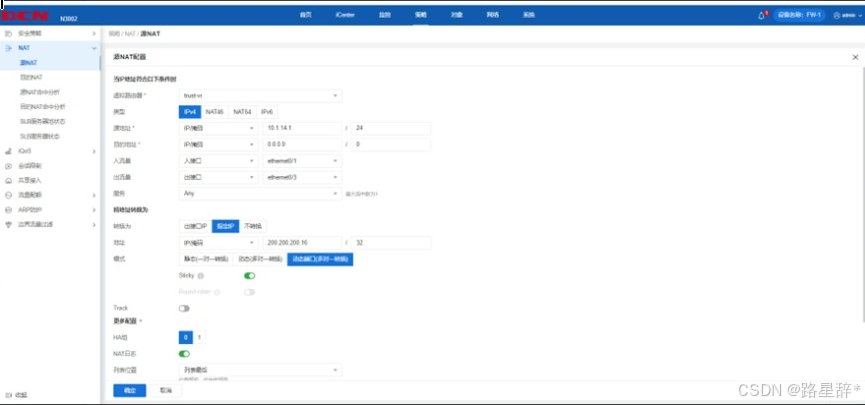
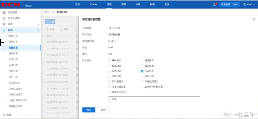
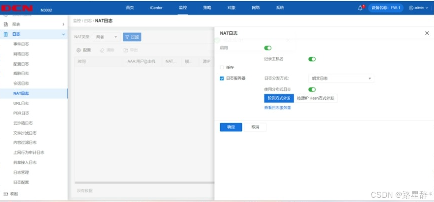
1.FW1 配置 ipv4 nat,实现集团产品 1 段 ipv4 访问 Internet ipv4, 转换 ip/mask 为 200.200.200.16/28,保证每一个源 ip 产生的所有会 话将被映射到同一个固定的 IP 地址;当有流量匹配本地址转换规则时 产生日志信息,将匹配的日志发送至 10.1.11.120 的 UDP 514 端口, 记录主机名,用明文轮询方式分发日志;开启相关特性,实现扩展 nat 转换后的网络地址端口资源。
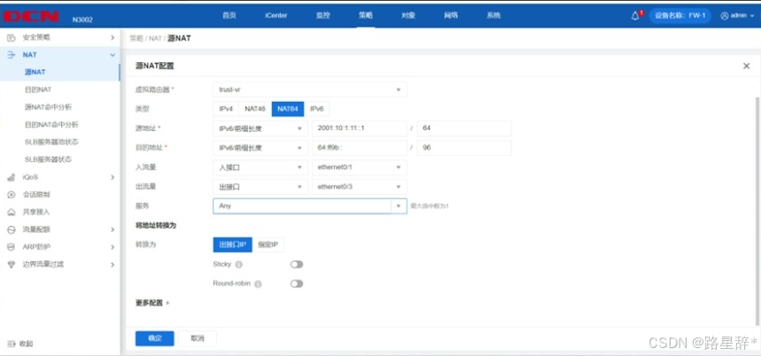
2.FW1 配置 nat64,实现集团产品 1 段 ipv6 访问 Internet ipv4, 转换为出接口 IP,ipv4 转 ipv6 地址前缀为 64:ff9b::/96。
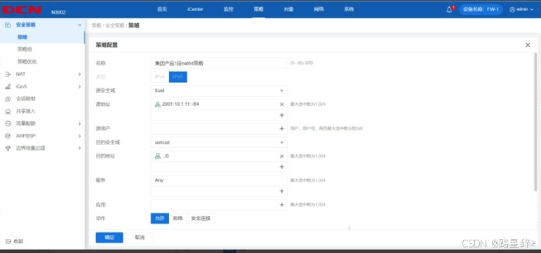
3.FW1 和 FW2 策略默认动作为拒绝,FW1 允许集团产品 1 段 ipv4 和 ipv6 访问 Internet 任意服务。

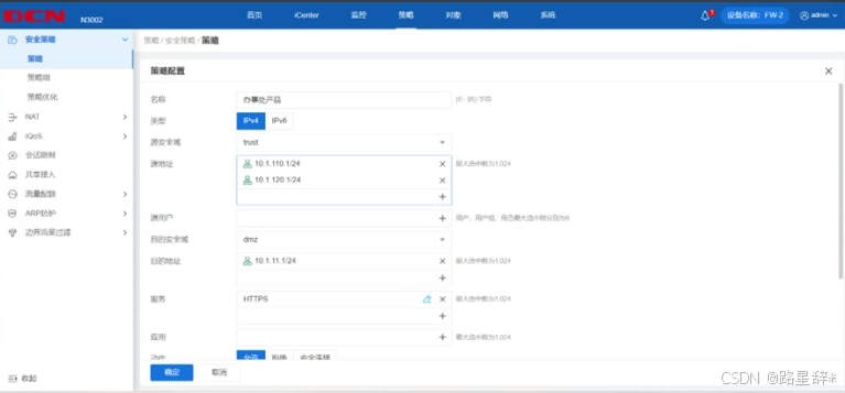
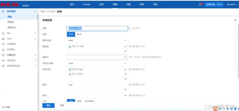
4.FW2 允许办事处产品 ipv4 访问集团产品 1 段 https 服务,允许 集团产品 1 段访问办事处产品 ipv4、FW2 loopback1 ipv4、SW3 模拟 办事处 loopback2 ipv4。
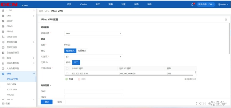
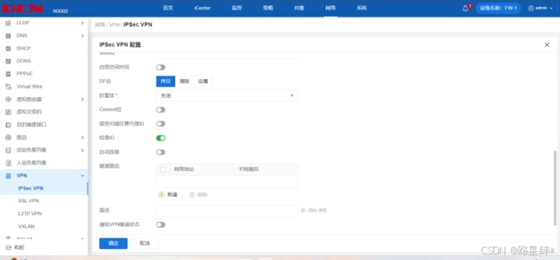
5.FW1 与 RT2 之间用 Internet 互联地址建立 GRE Over IPSec VPN, 实现 loopback4 之间的加密访问。
#RT2:
crypto isakmp key 0 Key-1122 address 200.200.200.2 255.255.255.252
crypto isakmp policy 10
authentication pre-share
encryption 3des
group 2
hash md5
crypto ipsec transform-set ipsec esp-3des esp-md5-hmac
crypto map ipsecmap 10 ipsec-isakmp
match address ipsecacl
set peer 200.200.200.2
set transform-set ipsec
interface Tunnel4
ip add 10.1.255.50 255.255.255.252
tunnel source 200.200.200.6
tunnel destination 200.200.200.2
ip route default 200.200.200.5
ip route 10.1.7.4 255.255.255.255 Tunnel4
ip access-list extended ipsecacl
permit gre 200.200.200.6 255.255.255.252 200.200.200.2 255.255.255.252 //'(配置
感兴趣流)
Int g 0/3
Crypto map ipsecmap //'最后一步外网口关联crypto map (这个地方吃过大亏)

FW1:
Ip route 0.0.0.0/0 200.200.200.1
ip route 10.1.7.4 255.255.255.255 Tunnel4配置路由
tunnel gre “gre”
source 200.200.200.2
destination 200.200.200.6
interface ethernet0/3
next-tunnel ipsec IPSEC
#interfae tunnel4
Zone “VPNHub”
Tunnel gre “gre” gw 10.1.255.50 (指向对端tunnel的ip)即本地网关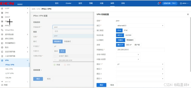

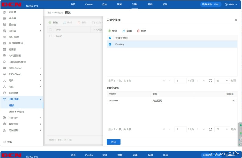
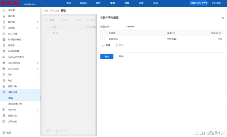
6.FW1 配置邮件内容过滤,规则名称和类别名称均为“DenyKey”, 过滤含有“business”字样的邮件。
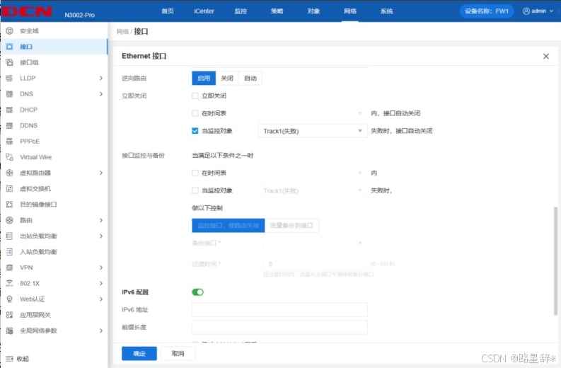
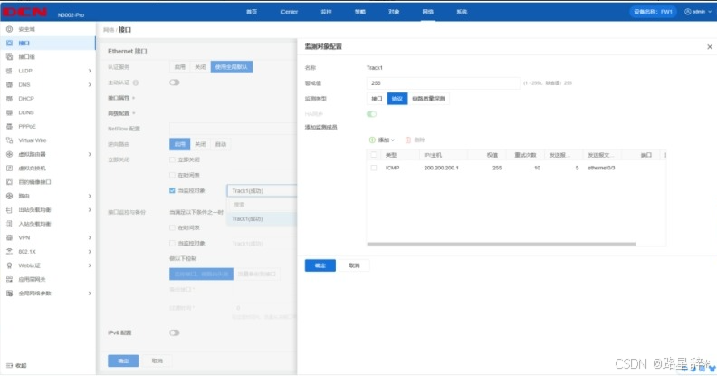
7.FW1 通过 ping 监控外网网关地址,监控对象名称为 Track1,每 隔 5S 发送探测报文,连续 10 次收不到监测报文,就认为线路故障, 关闭外网接口。
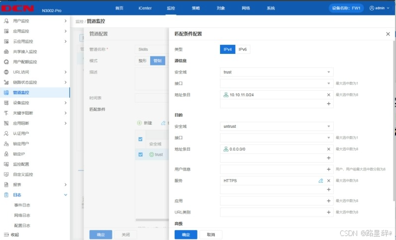
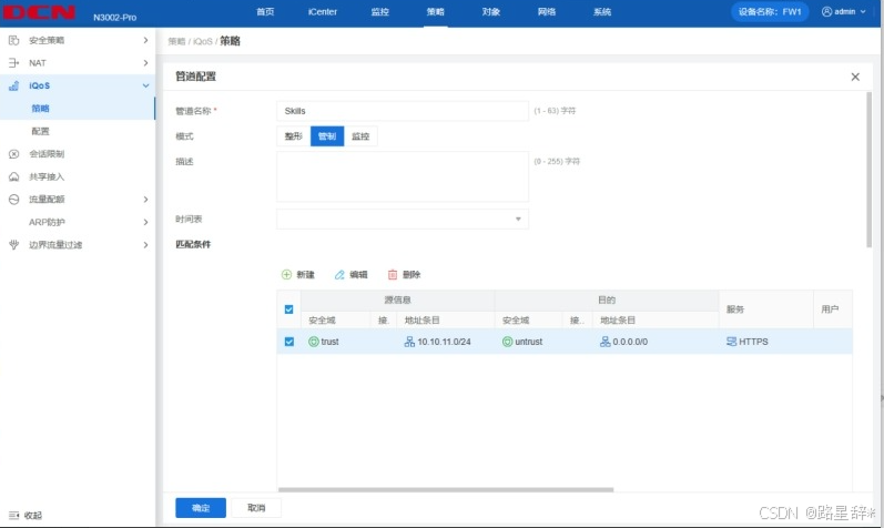
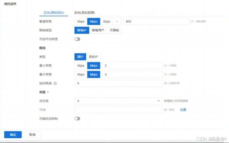
8.FW1 利用 iQoS,实现集团产品 1 段访问 Internet https 服务时, 上下行管道带宽为 800Mbps,限制每 IP 上下行最小带宽 2Mbps、最大 带宽 4Mbps、优先级为 3,管道名称为 Skills,模式为管制。